CHAP 1 - Introduction CHAP 2 - Some Basic Specs CHAP 3 - Locations of Major Equipment CHAP 4 - the "TRACS" Computer System CHAP 5 - the High Voltage, Auxiliary and Propulsion Systems CHAP 6 - the Low Voltage Systems and Batteries CHAP 7 - the Air System CHAP 8 - the Braking System CHAP 9 - the Suspension System CHAP 10 - the Trucks CHAP 11 - the HVAC Units CHAP 12 - the PA and Intercom System CHAP 13 - the Pantographs CHAP 14 - the Doors CHAP 15 - the Couplers CHAP 16 - the Lighting System CHAP 17 - the Destination Signs CHAP 18 - Winterization CHAP 19 - Operation CHAP 20 - Maintenance CHAP 21 - Floobydust
8.1 The braking system is comprised of the friction brakes, dynamic brakes, track brakes, and the air system. An FRA mandated trip stop system is also connected into
the system for emergency stops at interlocking points.
8.2 Added in 2004, with the completion of double-tracking the south end of the system (Camden Yards and south), ATC was added, which electronically transits a coded signal along the
rails to limit the top speed of the train. The signal operates at 2050Hz, and is modulated between 3 and 12Hz for speed information. The absence of modulation or of the signal itself will stop the
train. ATC was not added to the north end of the system (North Avenue and above) until after the double tracking was completed in October of 2005
8.3 During normal operation, the dynamic braking system provides the majority of the braking. Dynamic, or regenerative
braking, is accomplished through the reverse application of the motors, using them as generators. The power generated by the motors during this process is either sent out over the catenary for other vehicles
to utilize, or is dissipated in a rooftop resistor bank if the line is not “receptive” and the voltage exceeds 1050VDC. Dynamic braking is utilized from operating speed down to 3mph. The friction brakes
begin to apply at 5mph, so there is an overlap period where both are in effect between 5 and 3mph (you can feel a slight "bump" around 5mph when the friction brakes are activated). Dynamic braking,
of course, can only be used on the four powered axles, the two axles on the center truck use friction braking all the time.
8.4 All six axles have
friction brakes, otherwise known as disc brakes. ABB refers to them as friction brakes, so we will use that term for our discussion. The friction brakes are spring applied, air
released. This makes the brakes fail safe. The friction brakes are controlled by the computer through a "black box" located above the computer. This box houses the EBCU’s,
short for Electronic Brake Control Unit (Picture 8-1). There are two EBCU’s: one for the center truck, and one for the two power trucks. The center truck requires its own EBCU because of the different
braking rate required due to a lack of dynamic braking. Because of this, the center truck friction brakes are used all the time, and the brake pads wear out faster. To my knowledge, no-one has ever suggested
checking the springs for their "springingness" come overhaul time, for no spring ever keeps it's original tension. If the springs aren't up to the task, they would not be able to properly apply the brakes
in the event of an air system or braking system failure.
Picture 8-1 The EBCU's
8.5 Each axle has its own brake cylinder (5), rotor – or disc (2), and a pair of disc pads (3). The brake cylinder contains two brake pistons. One is for normal braking
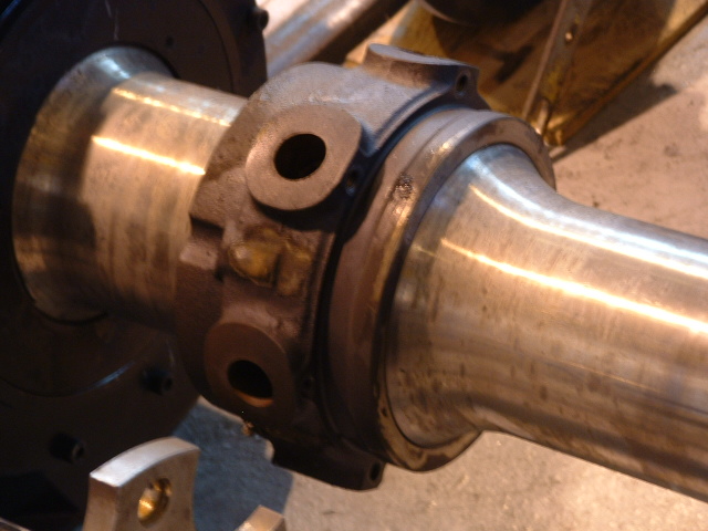
(red 7), the other is for cutting-out the brakes (red 8). The rotor is made up of two halves, bolted to a bulge in the axle (the bulge is slightly off center
of the axle - pictures 8-4 and 8-5). The rotor is approximately 2” thick, and 15” in diameter, and has cooling slots in between the two faces. The brake pads are like oversized disc brake pads for
a car, but much easier to replace. If the pads need to be replaced, you cut-out the brakes, and then use a screwdriver to snap a holding clip out of the way, and the old brake pad drops down. After
the new pad is in place, you go back up to the K91 locker, and flip the cut-out circuit breaker on and off two or three times to allow the auto-adjust feature to work its magic.
Picture 8-2 Disc brake rotor and pads
(1) the brake pad holding clips, (2) the rotor, (3) the disc brake pads, (4) the caliper, (5) the brake cylinder, (6) manual brake crank-off, (7) main brake air line, (8) cut-out air line.
Picture 8-3 Brake assembly
Picture 8-4 / 8-5 An axle before the brake rotor is installed
Picture 8-6 An axle with the brake rotor installed
8.6 When the brakes are cut-out on a truck, you have no friction brakes available for that truck, and the computer can not control them. There is a circuit breaker in the K91 locker for each truck
to accomplish this. The circuit breakers are safety tied with a railcar maintenance installed seal, so operations can determine if the operators have been at the cut-out switches doing things they have not been
told to do. The seals are checked routinely once a week during the weekly inspections.
8.7 A switch contact on the brake cylinder of each truck is wired to trainline 19/119, and goes into the computer on input #5 of board 6.3.189, via a 39V digital filter on board 6.2.
169. Since the contacts are in parallel, this means any of the brakes applied will give the computer an input, the signal name of which isBRKAPPL. The trainline is also connected to an
indicator on the operators panel that informs him the brakes are applied.
8.8 If the EBCU fails, and cannot activate the brakes, there is a “failsafe” signal that originates from the ECBU and goes to the computer. For the power truck ECBU, the signal
goes to input #14 of 6.3.177 (FBRFPT), and the center truck signal is input #13 (FBRFCT).
8.9 The brakes can be manually cranked off in the event absolutely nothing else will work to release the brakes. In the "B" cab of every LRV, there is
a special tool, or hand crank to do this. The hand crank has on the end of it, a 17mm socket, which in turn, mates with a 17mm stub sticking out of each brake caliper
(yellow 6 in picture 8-3). It’s not too difficult to crank
the brakes off, but it requires a little practice to locate the 17mm stub, especially if it’s cold, rainy, and dark outside! When only one axle has been cranked off, you will get a message on the FIS stating
that you have an incomplete manual brake release. Once all six axles are done, you will get a "manual brakes release" message displayed. I don't think the software has been fixed yet, so if
you check the FIS display as you crank off the trucks, you will notice that the computer doesn't really know which truck has been cranked off. Oooops! Great care has to exercised when the brakes are
manually cranked off, because there is NO WAY to stop a car if it starts moving on its own (other than track brakes). But then too, the track brakes may not work if you had to go to the trouble of cranking
the brakes off in the first place, So you need to be very careful, and aware of where youdo it! If you crank the brakes off on a grade, and the car is not coupled to another LRV or an
engine, it will get away from you!
8.10 The red needle on the operators pressure gauge shows the pressure going to either the "A" truck or the "B" truck, depending on which end you are
looking at. This gauge does not always show the entire picture, though. If you have released the brakes by using the cutouts, or if they are manually cranked off, these
gauges will not show that!
8.11 The braking rate is controlled by a number of factors: 1) The position of the master controller, 2) The speed of the train, 3) The weight of the car with passengers
aboard (weight readings are taken every time the operator issues a "close door" command), and 4) Wheel slippage. All of these factors are taken into account when the computer issues a braking
command.
8.12 There are two special valves associated with the brake system, SAV and SEV. The SAV valves (Figure 8-7) are used to position the brake shoes "near"
the rotor. There is an SAV for each truck. When the master controller is moved back to the coast position, air pressure is reduced to the brake calipers from their normal 90PSI.
The SAV valves sense this drop in pressure, give a quick dip of their own to the brake line, and this sets the brake pads only a millimeter or two away from the rotor surface. Automatic slack adjusters on
each caliper keep this distance at the proper setting. The SEV valves (Figure 8-x) are used to compensate for the long run from the brake rack in the "A" car to the brakes in the "B" car.
Picture 8-7 An SAV Valve
8.13 There are several extra air storage tanks underneath the car. Two of these are for emergency brake release purposes. If, for some reason, the operator
can not get a brake release, he, or maintenance personnel, can go into the K91 locker and cut the seals off the brake cutouts for each truck. The air tanks
are isolated from the primary air system by a check valve. The main air system can be completely bled down, and you can still release the brakes using the cutouts. Throwing a cutout actuates an air
valve, allowing tank pressure into a separate cylinder in the brake caliper assembly, thereby releasing the brakes. This also assumes you have 39V in the batteries to actuate the valves. In
instances where the batteries have also been depleted, there are several special battery boxes in the shop to allow these valves to be energized. They contain a 36V battery pack, and attach to the backside
of the cutout switches. Care has to be taken to prevent hooking up the positive side to the wrong side of the switch, because you could otherwise "try" to power the rest of the car from this
battery pack.
8.14 The track brake circuit is an emergency loop that is active whenever the LRV is keyed up. It takes a moment or two
for this circuit to normalize when you first key-up, and when you do, you can here the track brakes energize just ever so briefly. There are 4 operator actuated controls in each cab for the track brake
circuit: 1) a red mushroom, 2) a track brake push button switch, and 3) two switches at either extreme of the master controller. Of the four, only the mushroom is
directly connected into the emergency loop, the other three switches feed into the computer. There are three heavy duty relays, or contactors, that energize the track brakes. Each contactor has a set
of contacts, which are wired in series, and when all three relays have “picked”, or pulled in, it sends an input signal to the computer on input #10 of board 6.3.177, a 24V input, and the computer name for this
signal is TRACKAPP. Each pair of track brakes has a protection diode across the coils, and they are located in the same cabinet as the three contactors, A.U.K14.
Picture 8-8 Track brake
8.15 The track brake push button switch is a single switch mounted on the operators console. It feeds into the computer on input #6 of the 6.3.169 board, which is a 24V input.
It also feeds a trainline on coupler pins 18/118. The computer label for this input is TRACKBRK. Like most operator controls, the circuit is only active when a cab is keyed-up. Sometimes,
if track conditions warrant (slippery from water, for instance), the operator will use this switch to help stop. By pressing this button, sand will be ejected, and the track brakes will drop -- but propulsion
(or braking) is not effected. Operators use this button a lot on Howard Street when going southbound and there is even a small amount of dew on the rails.
8.16 The two switches on the master controller not only applies the track brakes, but kills the propulsion (if active) and eject sand. It does not, however, shut down the HV
system (open the main CB). The master controller switches go into the computer on input #21 of the 6.3.173 board, again, a 24V input. This function is not trainlined, as the computer will send out
commands over the ITDS.
8.17 The most drastic action comes from the use of the mushroom. By pressing this button, it not only kills the propulsion, but opens the main CB to assure that there is no power
available for propulsion. High voltage will be returned after a complete stop has been made (or, actually, zero speed has been reached). Figure 8-x is a simplified diagram of the emergency brake loop
circuit. Sheets 901-902 show the same system. The track brakes should be adjusted for a minimum of 8mm clearance between the rail and bottom of the magnets, and a maximum of 10mm. There are
two collars associated with the track brake adjustment. Adjust the lower collar for the proper 8-10mm height above the rail. The upper collar adjusts the amount of
preload, or, spring tension there is to bring the track brakes back up after being applied. There is an official adjustment procedure for the preload, but if you can, with a little bit of
trouble, pull one end of the track brake down with two hands, it is usually in the ballpark. Figure 8-x is a track brake.
8.18 The trip stop units are not really part of the braking system per se, but I didn't have any other place to put them. Under
the car, mounted to the pilot bar of the lead truck, is a partially yellow painted box. This box contains a pickup coil, that senses the presence of a track mounted magnet. The magnets are located
along the system at interlocking points: places where, if an operator makes a wrong decision to proceed against a red signal aspect, the trip stop system will bring the train to a halt (does the same thing as
hitting the mushroom). As you can imagine, if a train is going into single track territory and it has a red signal, it usually means that something else is already ahead of it, providing the potential
for an accident.
Picture 8-9 Trip stop unit
8.19 The trip stop controller, or brains, is located, above the circuit breakers in the K50 locker of each cab. The unit has two push buttons on it, release and
reset. Once the trip stop system has been activated, the track brakes will come down, the sonalert on the operators console will blast at you, and the reset button will light up
(white). By pressing thereset button and holding it in till the track brakes come back up, the unit will reset. The reset function is controlled by a
thermal element, this is why it doesn't take as long to reset the second and third time the system is tested during a weekly inspection. If you are aware of a trip stop situation before you get to it,
you can press the release button. The button will light up for approximately 25 seconds, and during this period, the vehicle can pass over the track mounted
magnet without actuating the system. Dual counters record the numbers of times each button has been pressed, and SUPPOSEDLY, only railcar maintenance personnel have access to keys to reset the
counters. When a trip stop occurs, the FIS display will show "F17 TRIP STOP VIOLATION”.
8.20 The sensor head of the trip stop system is located under the cab floor, and is supported by a bracket which places it in close proximity to the rail head height. The case is a heavy duty
cast aluminum housing, partially painted bright yellow.
8.21 The associated trip stop actuator on the tracks is also a brightly yellow painted cast aluminum housing, placed slightly off center to the right for the direction of traffic it is governing.
With the advent of ATC operation, they have all been removed from the right-of-way except as noted below.
8.22Important Note: In 2004 on the south end of the system (below Camden station) after the line had been double tracked, and in 2006 on the north end
(above North Avenue), ATC operation of the trains was put into effect. This is a system whereby the trip stop units are no longer utilized, except at the ends of the system at Hunt Valley and BWI
Airport (sorry, the name was changed in 2005, but it will always be BWI Airport to me).
8.23 The dead man function is considered part of the braking system. The lever on the master controller must be kept pushed down in
order for the computer to recognize that there is an operator present. The input from this switch goes into the computer on input #11 on board 6.3.177, which is a 24V input, and carries the
designation DEADMAN. If the operator removes his hand from the lever, the sonalert will start beeping after 3 seconds, and in an additional five seconds, will put the train into an emergency
stop. The switches in the two cabs are in parallel, but since they are normally open, do not have to go through a set of keyed-up contacts in order to prevent them from interfering with each other.
8.24 Sanding - nothing has been mentioned about sanding the rails so far. Sanding is both a manual and automatic function. Both operations however, are controlled by
the TRACS computer. There is a button on the operators console to manually activate the sanding - it is a trainline function, and goes to input #11 on board 6.3.177, a 24V input, and its signal name
is MANSAND. The push button switch is enabled by a set of contacts on the keyed-up relay. There are two outputs from the computer, one for each end. The control for the A end
originates from digital output #2 of board 6.3.161, and the signal name is SANDA, while the B end is output #3 (SANDB). Both outputs are filtered by the digital filter board 6.2.161.
If the computer detects a slip/slide condition during either acceleration or braking, it will issue a sanding command automatically.
8.25 A few notes about the mainline testing of the brakes. After certain “events”, the car has to have the brakes tested in what is called a brake
rate test. The graphs obtained from these tests are used to determine if the car is braking and accelerating within specifications. Brake rate tests are performed: 1)
after an accident, 2) after the wheels have been trued (changing the size of the wheel), and 3) after every annual inspection. The tests are performed on mainline in certain areas designated to have a
specific grade. There are 4 sets of tests performed, with each set having one test done uphill and one test
performed downhill. The tests are: 1) Dynamic braking, 2) Friction braking, 3) Track brakes, and 4) Acceleration (OK, so it's not purely a brake test).
The dynamic brake rate is checked from an operating speed of about 40mph. When reached, the operator applies full service stop braking, bringing the car to
complete stop. The specified (dynamic) braking rate on a level track is 3mph/sec. The friction brakes are checked by first cutting out one of the propulsion modules. This not only limits the
top speed to approximately 25, but also does away with the regenerative braking. To check the track brakes, the operator takes the car up to 10mph or so, and slams the master controller into
full stop. As for the acceleration check, the operator moves the master controller to full power, and we measure
the amount of time it takes to get to 40mph (the acceleration rate is supposed to be 3mph/sec on a level track). These tests, of course, are only performed at the AW0 weight condition, but the results
are supposed to be guaranteed up to the AW2 level (see the next section for a description of the weight loads).
 NEXT Chapter ►
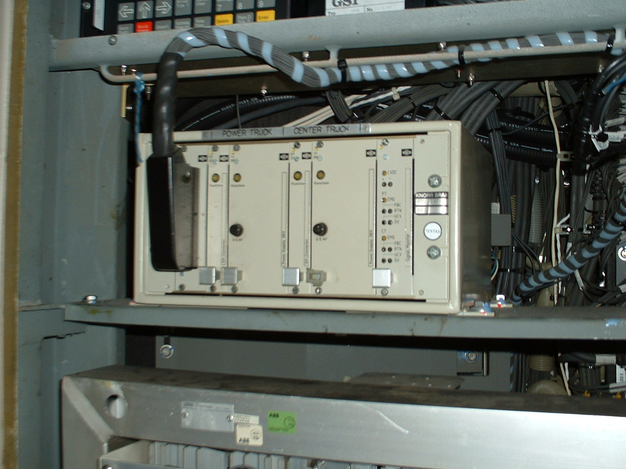 Picture 8-1 The EBCU's
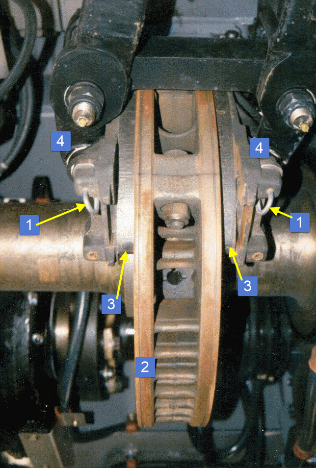 Picture 8-2 Disc brake rotor and pads
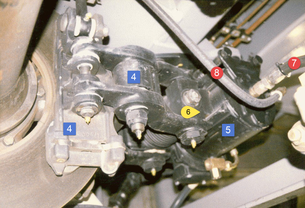 Picture 8-3 Brake assembly
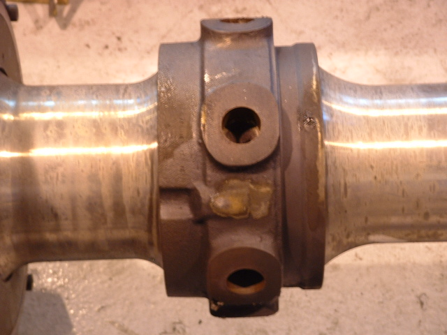
 Picture 8-4 / 8-5 An axle before the brake rotor is installed
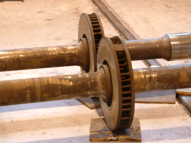 Picture 8-6 An axle with the brake rotor installed
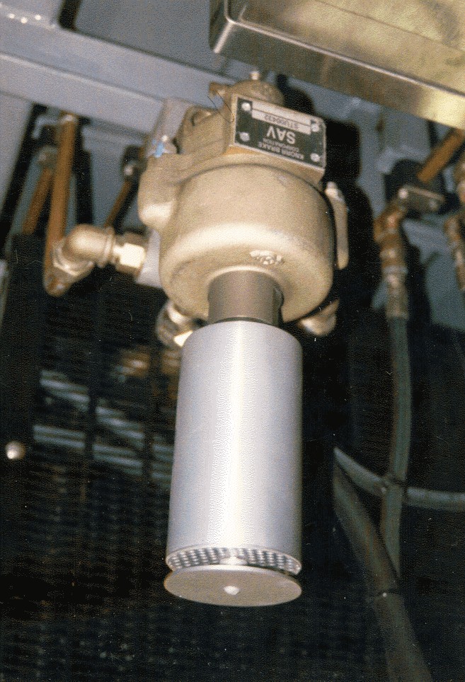 Picture 8-7 An SAV Valve
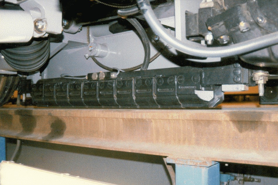 Picture 8-8 Track brake
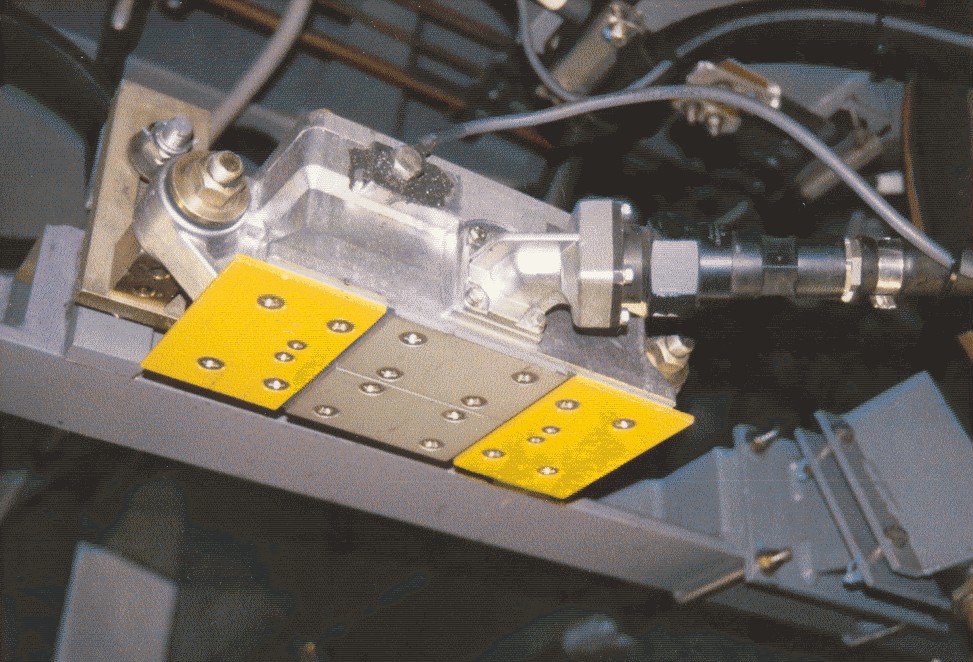 Picture 8-9 Trip stop unit