CHAP 1 - Introduction CHAP 2 - Some Basic Specs CHAP 3 - Locations of Major Equipment CHAP 4 - the "TRACS" Computer System CHAP 5 - the High Voltage, Auxiliary, and Propulsion Systems CHAP 6 -
the Low Voltage Systems and Batteries CHAP 7 - the Air System CHAP 8 - the Braking System CHAP 9 - the Suspension System CHAP 10 - the Trucks CHAP 11 - the HVAC Units CHAP 12 - the PA and Intercom System CHAP 13 - the Pantographs CHAP 14 - the Doors CHAP 15 - the Couplers CHAP 16 - the Lighting System CHAP 17 - the Destination Signs CHAP 18 - Winterization CHAP 19 - Operation CHAP 20 - Maintenance CHAP 21 - Floobydust5.1 The Hi-Voltage system takes in everything from (but not including) the pantograph down to the two propulsion modules, the auxiliary converter, and the battery charger. See figure 5-1
for the basic schematic.
Figure 5-1 Basic High Voltage Distribution
5.2 The high voltage leaves the pantograph and goes into a small rooftop mounted enclosure which contains the main fuse (HV.FSLIN) and the overvoltage protection diode (HV.LALIN). Refer
to figure 5-1 and circuit diagram 211. The fuse is a 1500 amp unit, I have never heard of one blowing. From there, the Hi-V wires go down thru the roof, between two windows on the left side of the car,
and down to the knifeswitch (HV.DCLIN) in the Q22 locker. This switch provides a means for supplying shop power through J1, or isolating the system completely from hi voltage. The switch, along with J1,
is located to the right in the Q22 locker, as viewed from the east side of the car.
5.3 Next, the current flows through two current sensors. The first one (HV.CMULIN) sends an analog signal to the TRACS computer, indicating the total current being used by the car.
The second current transducer (HV.CMUDIF) is a differential unit, and sends a digital output to the computer if the current coming into the LRV (through the pan) is not the same as what's going out (through the wheels).
All supply current coming from the pantograph and return current headed for the wheels goes through this sensor.
5.4 From the current sensors, the Hi-V splits and goes to the main circuit breaker, the floor heaters (diagrams 1211-03), and the battery charger (diagram 701). The main CB is located to
the left in locker Q22, in an "isolated" chamber. This CB (HV.CBLIN) supplies power to the propulsion and auxiliary modules. The main CB is closed thru the operation of two relays, HV.RLLCB
and HV.CRLCB, both in the Q22 locker (diagram 263). The RLLCB relay is controlled by the TRACS output LINEBHLD (board DIGOUT2/6.3.161 - output 10), and is referred to as the relay line circuit breaker
hold. This relay has three sets of contacts in series (for redundancy), is connected to BP63 on one side, and stays energized as long as the main CB is required to be closed. The other relay, CRLCB,
only energizes long enough to pull the main CB in, and then is de-energized. It is called the contactor line circuit breaker close relay. It is controlled by TRACS output LINEBCL (board
DIGOUT2/ 6.3.161 - output 9). Both of these TRACS outputs, by the way, are filtered by the DOF12 board (6.2.161). The CRLCB relay also uses three sets of contacts in series. Across the three
contacts, is a holding resistor, HV.REECN, which reduces the holding current through the main CB coil once the CRLCB relay opens (this is to reduce the heat dissipation).
5.5 Across the main CB is another circuit designed to supply a small charging current for the line capacitor, so the main CB doesn’t have to bear the brunt of the inrush current, and chance
welding the contacts. This relay (HV.CRCH) closes for about a half a second before the main CB is closed, to charge the Hi-V capacitor through charging resistor HV.RECH. This relay is driven by an
output from the computer, CHARGCL (board DIGOUT2/6.3.161 - output 1), via an output filter (board DOF12/6.2.161)(diagram 265).
5.6 After the main CB, comes the line inductor (HV.IDLIN). This component, along with the line capacitor, helps to smooth out spikes and the like coming in from the catenary. The
inductor is mounted inside its own housing, with screened ends to provide for cooling. During the winter months however, covers are placed over the screened sides to keep snow out. During the bad
March snowstorm of the 95-96 winter, snow got packed up into the line inductors, and eventually started blowing them up, one by one, once the snow started melting.
5.7 There are two propulsion modules, referred to as PMA and PMB. Each module powers two asynchronous traction motors, which are wired in parallel. The purpose of the propulsion
modules is to convert the 750VDC into a three phase AC signal for the motors. The propulsion modules are located on the east side of the LRV in the "B" section, under the skirt that has "
PMA" and "PMB" printed over it on the car body. Removal of the modules is fairly simple. It requires a 17mm socket to remove two securing bolts along the bottom, and a 6mm ball type
Allen driver to remove the input connector. Once these are removed, the module will fairly easily pull out on a set of slide rails. It is suggested that either an overhead crane or forklift be used
to pick up the module, for it weighs around 450lbs. Here are some expanded specs for the modules:
A Normal line input voltage is 450-950VDC.
B Inputs for rated motoring output is 700-950VDC at 1650A peak.
C Inputs for rated braking output is 880-950VDC at 1930A peak.
D RMS input current (1 hour) is 710A.
E Maximum rated output power at 750VDC is 400kVA each
F Maximum power at 88VDC is 950kVA each
G Rated phase current for each leg of the inverter is 370A.
H Maximum phase current for each leg is 800A.
I Output voltage is 0-585VAC.
J Motor frequency is 0-155Hz.
K Maximum commutation frequency is 400Hz.
L The GTO's are rated at 1800V and 2000A.
M The associated line inductor is rated at 0.75mH.
N The associated line capacitor is rated at 37.6mF.
O The associated brake resistor is 4x 1.45 ohms.
5.8 Each propulsion module obtains its drive signal directly from the TRACS computer, see drawing 5-2. The drive signals are fed to GDU boards on the propulsion module chassis. There
are eight GDU (Gate Drive Unit) boards. Six are for the inverter GTOs and two are for the overvoltage crowbars.
5.9 During acceleration, the voltage and frequency is modulated by the TRACS computer. Many factors are considered when the computer calculates the drive values. Some of these are
the speed of the vehicle, position of the master controller, line voltage, tractive effort requirements and rail conditions. The GDU's not only provide drive to the GTOs, but they provide isolation between
the low voltage computer outputs and the high voltage GTO circuits. Pulse transformers are used for isolation. Tractive effort is constant up to 20mph, and above that, it is reduced (since the greater
tractive effort is only needed to get the train moving from a dead stop). The acceleration rate is weight independent up to weight condition AW2. Figure 5-2 shows some sample drive waveforms.
5.10 The GTO’s mentioned in paragraph 5.8....GTO stands for Gate Turn Off thyristor. They are similar to a standard SCR, except that both the turn-on point AND turn-off point can be
controlled (with an SCR, once it has been turned on, it can only be turned off by reducing the voltage across it to zero, or by reversing the current flow, effectively reducing it to zero). There are two
GTOs in each phase leg, in a push-pull arrangement. They are a matched pair, so if one blows, they both need to be replaced (that can get expensive, for one GTO from ABB is a thousand bucks.......Ouch!).
Figure 5-3 is a basic schematic of the propulsion and auxiliary modules.
5.11 There are a couple of benefit derived from using GTOs, although the first one is mainly a result of using AC motors which only need two phases to be reversed to in order to change direction
-- that is accomplished in software and the drive signals. You do not need contactors to change the output lines when changing direction, or when you go from propulsion to braking.
5.12 When the cars are braking, the process is reversed, and the motors are used as generators (alternators, actually.....but ABB calls them generators). This is known as dynamic
or regenerative braking (sorry if I repeat myself, this may be somewhere else in the text). The output is rectified and put out onto the overhead wire, but only if the line is receptive.
A receptive state would be one where the voltage is low enough (due to another train being in the same "block") to need the extra power. If there is no other car on the sub-station circuit, the
voltage may be sufficiently high already. In that case, the overvoltage choppers in the propulsion modules would direct the output to the rooftop mounted braking resistors. Excess line voltage can
also be dissipated through the rooftop resistors. Railroad engines, by the way, have used dynamic braking since the 50's, and if you hear ‘em going by with rooftop blowers going at full blast, they are
cooling down the dynamic brake resistors.
5.13 Sometimes, an event occurs that they (ABB) call a commutation failure. This refers to a situation where both GTOs of one leg are "ON" at the same time. This
would result in a dead short across the 750V catenary. If this happens, there is a crowbar thyristor that fires to limit the current through the GTO's (they shunt current away from the
GTO's). The thyristor is across the input to each pair of GTO's. An inductor is placed in series to help limit the amount of instantaneous current going the thyristor. Also helping in
the task of limiting current through the GTO's, is a small value resistor placed in series with the DC-link capacitors), and the main line inductor. Hopefully, the commutation failure fault will not last any
longer than one switching cycle. The frequency at which the GTO's are turned on and off is referred to as the commutation frequency. A commutation is when one GTO is turned on and the
other one turned off. Figure 5-4 is a basic crowbar circuit.
Figure 5-4 Basic Crowbar Circuit
5.14 The GTO's are protected by snubber and clamping components. These components are shown in drawing 5-2. The snubber and clamping caps and diodes help absorb transients generated
by the switching action of the GTO's. The Di/Dt choke limits the in-rush current when the GTO is turned on (otherwise it would damage itself at turn-on). The clamping resistor discharges the clamping
caps in between cycles.
5.15 Operation of the auxiliary modules is much the same as the propulsion modules, except they don't have to be concerned with providing dynamic braking. There is an additional function
for the aux module: It contains a voltage measuring LEM, whose digital output feeds the TRACS computer. This information is used by TRACS to compute things like GDU drive waveforms, propulsion rates, and
braking rates.
5.16 Another use of GTO's in both the propulsion modules and the auxiliary converter is for brake choppers, or overvoltage choppers. There is one in each propulsion module,
and two in the aux module. The basic circuit consists of the GTO in series with one of the four rooftop mounted resistors. The resistors are connected directly across the 750VDC line, via the GTO’s.
These GTO's, like all the others, are controlled by the TRACS computer. They are switched on and off at a rate of 200Hz, and the four are switched in sequence (so no two are on at the same time). The
computer controls the width of the "on-time" to adjust the amount of braking or overvoltage protection needed, from almost nothing, to almost "fully on" ("fully on" would be a period
of 1.25ms). Figure 5-5 is a simplified circuit of a single brake chopper circuit. Figure 5-6 is the switching waveform driving the choppers. A cautionary note: One side of the resistors is
tied to the +750VDC line. So whenever you are on the rooftop, you should consider them live even if there is no overhead power. The car could be powered from a "shop bug", and the resistors
would be HOT!!! (We found out about this the hard way - soon after getting the cars, someone did get zapped this way).
Figure 5-5 Basic Brake Chopper Circuit
Figure 5-6 Brake Chopper Drive Waveforms
5.17 There is one last circuit used for overvoltage protection. In case the brake choppers fail or can't do the job because of an excessively high line condition,
this circuit will fire. The circuit contains an SCR, fired by a special break-over diode (BOD) connected to its gate. When the line voltage reaches 1200V, the BOD will fire, trigger the SCR, and
discharge the DC-link capacitors, thereby opening the line breaker. This circuit operates independently of the computer. Usually, when this circuit triggers, it wipes out several components
and the entire module needs replacement. The module sits (kind of) behind and to the left of the battery charger. Figure 5-7 is a simplified circuit of the overvoltage protection circuit. There
is also an input circuit that allows TRACS to fire this circuit if it feels things are getting out of hand. Notice that all of the protection circuits are all very similar.
Figure 5-7 Basic Overvoltage Protection Circuit
5.18 Each propulsion module has three current measuring LEM's. One is for the total current consumed, and the other two measure the outputs of two of the phases (the third phase being
calculated).
5.19 Each propulsion module has its own hi-v contactor on the 750 volt input. The contactors are energized, as part of the “auxing up” procedure, after the TRACS computer has
decided the DC-link (750 volts) is present. If things are quiet, one can hear the contactors pulling in shortly after the AUX ON button is pushed, and then you will hear the fans starting up.
5.20 When you throw a PMA or PMB cutout switch in the K91 locker, it tells the computer to disable the propulsion module by not allowing the contactor to energize. When one propulsion
module is shut down, the speed of an LRV is limited to 25mph, and you have no dynamic braking available.
5.21 Here's an interesting little tidbit. In the event that the pantograph bounces off the wire, or the car goes over an insulated-joint (IJ), the computer senses this
loss of high voltage. It quickly sets the motors up for dynamic braking, in an effort to maintain a more-or-less constant high-voltage.
5.22 Each propulsion module has its own set of DC-link capacitors. There is a set of three of them, placed in series for redundancy. Along with these capacitors
is a circuit to detect if one of them has shorted. It reports to the computer. If one of them does short out, the computer opens the line breaker, discharges the DC-link capacitors through the brake
choppers, and disconnects the bad propulsion module. With only two of the capacitors in series, they can only withstand the high voltage for a short time since the imposed voltage has gone up by 50%
on each one. The three capacitors are supposedly matched and should be replaced as a set. The DC-link capacitors have a resistor and diode in series with them. The resistor limits discharge
current in the event of a commutation failure. The diode shunts the resistor to allow the capacitors to get charged without the series resistance.
5.23 There are temperature sensors on propulsion modules and the aux converter. Their purpose is to detect an overtemperature condition in the power semiconductors.
The three values are constantly monitored, and should be similar. If one is value is considerably different, that sensor is considered faulty and replaced.
5.24 The external and internal cooling fans have both circuit breakers and over current sensing relays in line. They all report to the TRACS computer. If a blower
motor fails, it will shut the high voltage down. If it is really hot outside, and an increase in cooling air temperature is sensed by the above mentioned temp sensors, it will also shut down the high
voltage. To add to the confusion (if you aren't already), the external blower motor is mounted internally to the cooling duct, and the internal blower motor is mounted on the outside of the cooling duct.
5.26 Although the battery charger is technically considered part of the high voltage system, it will be covered in the following low voltage section.
Are you still with me?
Picture 5-1 Main AC distribution
This photo was actually taken to show damage incurred in transit from the ABB factory in New York..... ooooops.
 NEXT Chapter ►
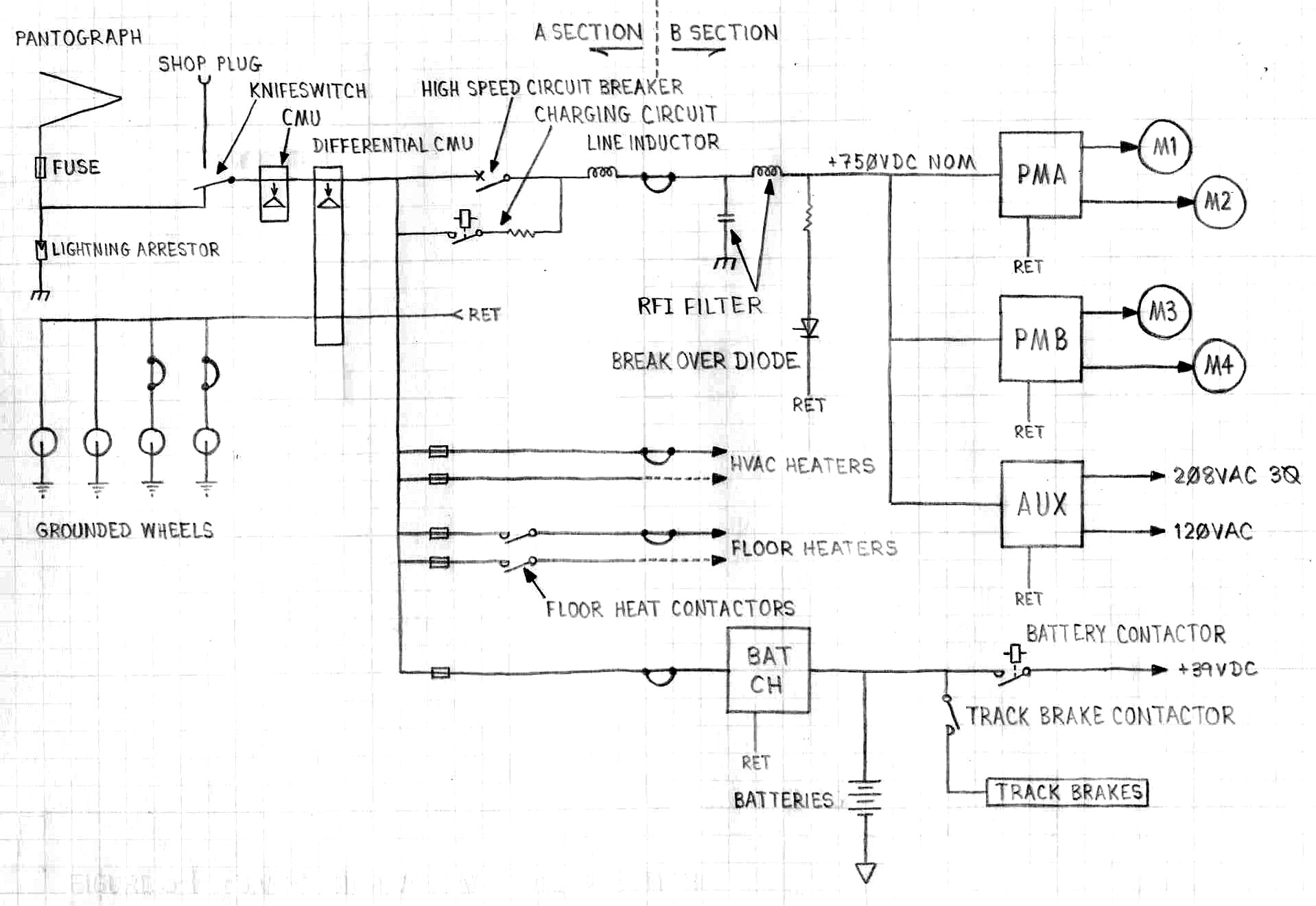
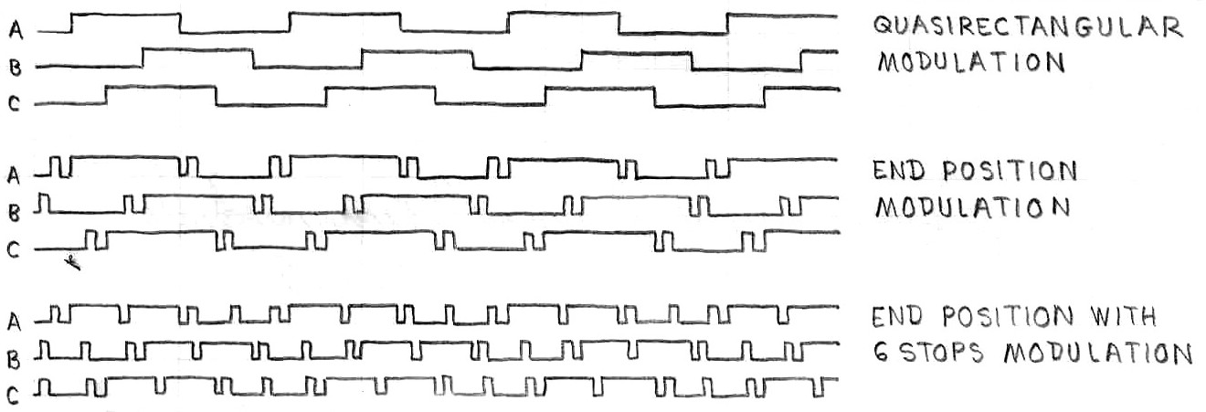
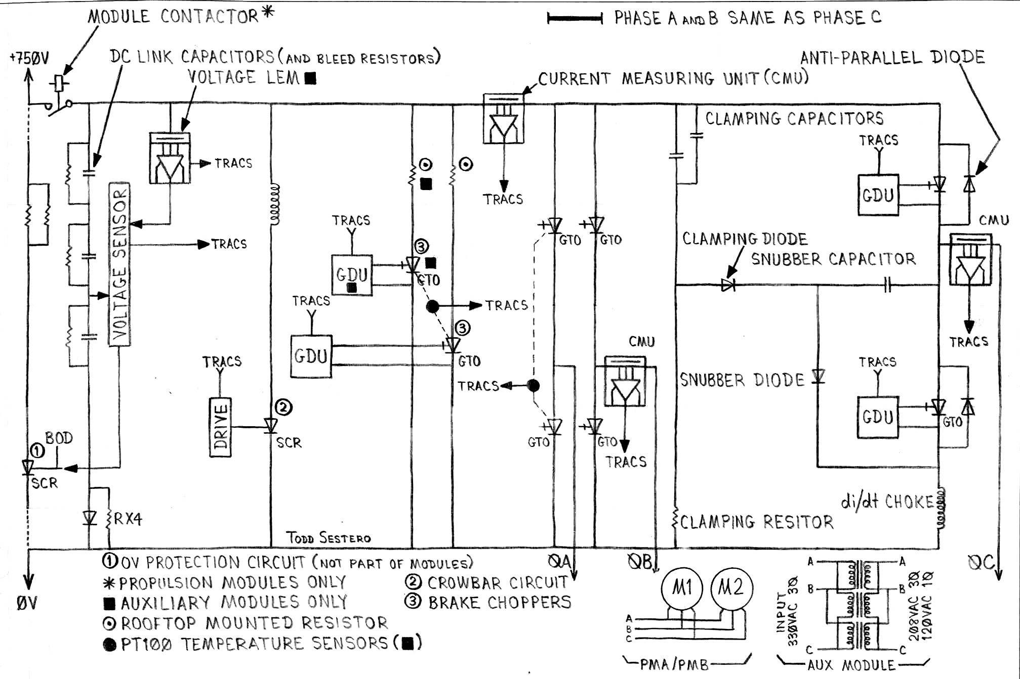
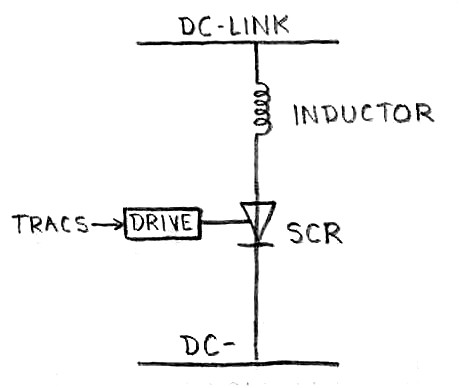 Figure 5-4 Basic Crowbar Circuit
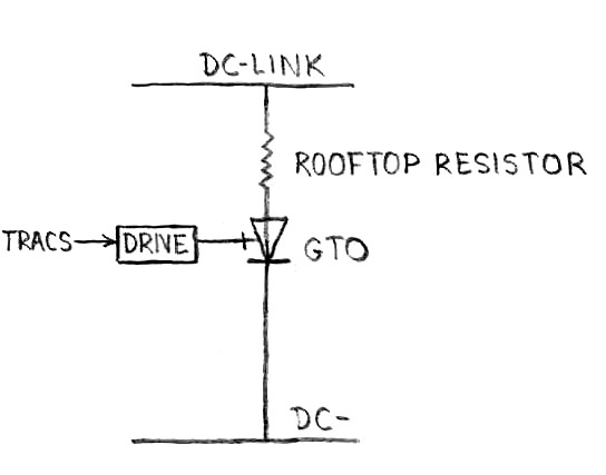 Figure 5-5 Basic Brake Chopper Circuit
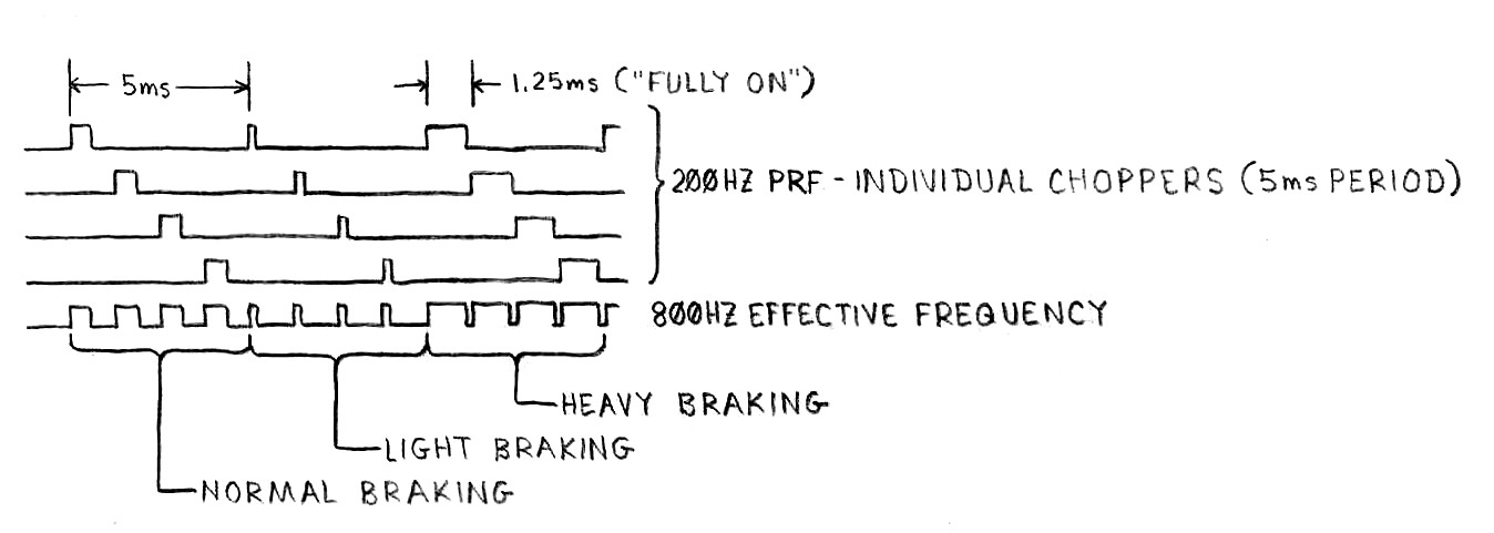 Figure 5-6 Brake Chopper Drive Waveforms
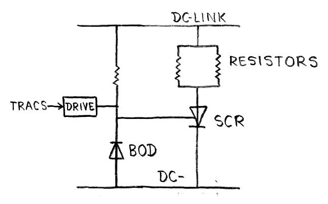 Figure 5-7 Basic Overvoltage Protection Circuit
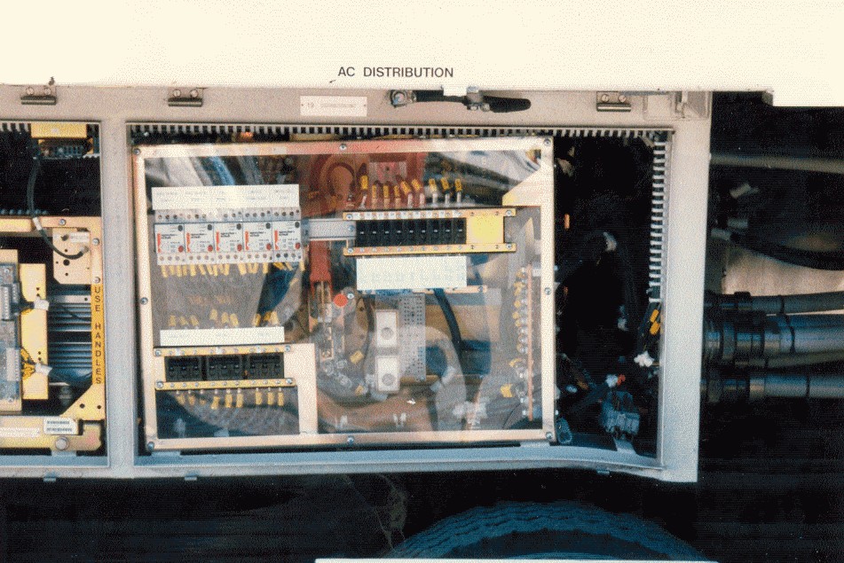 Picture 5-1 Main AC distribution