CHAP 1 - Introduction CHAP 2 - Some Basic Specs CHAP 3 - Locations of Major Equipment CHAP 4 - the "TRACS" Computer System CHAP 5 - the High Voltage, Auxiliary and Propulsion Systems CHAP 6 - the Low Voltage Systems and Batteries CHAP 7 - the Air System CHAP 8 - the Braking System CHAP 9 - the Suspension System CHAP 10 - the Trucks CHAP 11 - the HVAC Units CHAP 12 - the PA and Intercom System CHAP 13 - the Pantographs CHAP 14 - the Doors CHAP 15 - the Couplers CHAP 16 - the Lighting System CHAP 17 - the Destination Signs CHAP 18 - Winterization CHAP 19 - Operation CHAP 20 - Maintenance CHAP 21 - Floobydust
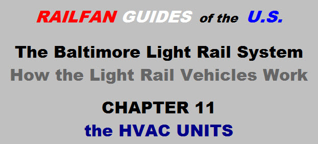
11.1 Each "car" of the LRV has its own HVAC unit - they are rated at 8 tons of cooling. If you are not familiar with the term HVAC, it
stands for Heating, Ventilation, and Air Conditioning, and is used in the industry to denote a unit that can provide all three functions. The units run off
of 220VAC, 3 phase for the compressor and blower motors; 39VDC for the PLC and control circuits; and 750VDC for the heaters strips. There is a 39VDC breaker in the K91 locker for each unit. Turning
these breakers off will shut the HVAC units down. Turning off the AC breakers in the K89 locker will do the same thing.
Picture 11-1 The two HVAC units on the roof
Picture 11-2 The cooling end of the unit
Picture 11-3 The heating and control end of the unit
11.2 Functionally, there is really nothing out of the ordinary about the units that you can't read about in any refrigerating manual, so I will not spend any time discussing the operation of
the refrigeration cycle.
11.3 The units mount to the rooftop, and sit atop six mounts. These mounts provide some vibration isolation to the car. The mounts use 3/4" bolts to bolt them to the roof.
The same bolt is used to hold the HVAC units to the mounts. Although there are six mounts, only five are bolted from the HVAC side, because the last bolt is in a really hard place to get to (expansion coil
is in the way). To take the units off the roof for service: 1) take out the five or six 3/4” bolts, 2) disconnect the ground strap from the HVAC chassis (9/16" bolt), 3) disconnect the three power
cables, and 4) remove the temperature sensor from it's slide mount and place it in the bottom of the HVAC unit. When placing the HVAC back on the roof, it's always a good idea to rotate the squirrel cage
blower to make sure it spins freely before and after you tighten the 3/4" bolts. The units weigh around 3000 pounds, so I wouldn't stand underneath them when they are swinging from an overhead crane :-)
Picture 11-4 A HVAC unit in the maintenance shop
11.4 Maintenance access to the HVAC units from the inside of the LRV is through a swing down roof panel that doubles as the return air vent (one is between doors 2 and 7, the other is
between doors 3 and 6). The panels use the "47" key, and once unlocked, there are two safety chains holding it up.
11.4.1 Through this panel, you have access to:
a) the return air filters.
b) the maintenance panel and test switch
c) the power supply cables
d) the heater fuse
e) the contactors and limit switches
f) the PLC.
Picture 11-5 the PLC (1) and maintenance panel (2)
11.5 The HVAC units have a special service switch, located at the bottom of the unit on a maintenance panel. This makes it convenient to reach
from inside the LRV. It has four positions:
a) Normal - is at 12 o'clock position
b) Cooling - at the 9 o'clock position-this forces the unit into the cooling cycle, bypassing some of the normal safeguards
c) Heat 1 - at the 3 o'clock position-this position forces half of the heater strips to come on
d) Heat 2 - at the 6 o'clock position-this position turns on both sets of heater strips.
11.6 The maintenance panel can be seen in both pictures 11-5 and 11-6, and has
six indicator lamps mounted on the front face of it. The 39 volts and interface cable also
plug into the front of this panel.
11.6.1 Looking at the maintenance panel lamps can be helpful in quickly determining a number of the problems:
a) two are for heating
b two are for cooling
c) one is for a supply air fault
d) one is for the compressor fault
11.6.2 The maintenance panel also has a reset switch for compressor faults.
Picture 11-6 Remainder of the relays and controls
11.7 When the switch is moved in and out of the HEAT 2 position, you should be able to see light (from arcing) coming out of the heating contactors, indicating that all four of the
heating elements are good. There are two contactors, each with two sets of contacts. Checking for the sparks is a quick way to determine if any of the elements have opened up or not (their usual
failure mode). If the contacts shorted out, the heat would never shut off. Putting the switch into the cooling mode bypasses the six minute timer, instantly energizing the compressor. If you
forget and leave the service switch in any of the test positions, the PC will disregard its setting after 15 minutes and go into the normal mode.
11.8 The system uses 20 pounds of R-22 refrigerant. The HVAC shop has the necessary recycling equipment needed to please the EPA and nothing is lost to the atmosphere during
maintenance. Originally, the units were rated at 6 tons each, but new expansion valves were installed during the 1995 season to up the rating to 8 tons. The two expansion valves can be individually
energized to adjust for the amount of cooling needed in relation to the outside temperature.
11.9 The HVAC units use a custom designed PLC (Programmable Logic Controller) for operation. The PLC is seen at the top of picture 11-5, above the
maintenance panel (the box with the 6 lights on it).
11.9.1 The PLC has inputs from the:
a) low pressure switch.
b) high pressure switch.
c) loss of air movement in the heat exchanger microswitch.
11.9.2 The PLC has several controlled outputs, they are:
a) the compressor motor.
b) the heat contactors.
c) the lamps on the HVAC annunciator panel.
11.10 Heating is performed by electrical heater elements, as seen in picture
11-7. There are four of them, and are wired so that two come on for "low" heat, and all four of them
come on for "high" heat.
11.11 There are only two HVAC faults that get reported back to the TRACS computer: a General Fault, and Compressor
Failure.
Picture 11-7 The heater elements and blower fan
11.12 As far as the cooling and heating cycles go, they are controlled by the two temperature sensors (and the PLC, of course). One is a single setpoint sensor, for monitoring the inside
temperature, and is located on a slide mount just above the ceiling access panel. The other sensor (a dual setpoint version) is mounted on the inside of the chassis, to your left as you look at the
"maintenance panel", and measures the outside air temperature.
11.12.1 The heating and cooling cycles are:
a) The range of "hot" down to 72 is strictly cooling.
b) Between 68 and 65, both the heating and cooling come on, to remove condensation from the air.
c) Below 64, one set of heaters come on, and below 60, both set of heaters come on (remember, there are two contactors for heating).
d) The A/C units that came with the original 35 cars are useful up to about 105 degrees, above that, they can not keep up the demand (I guess they need 10 ton units like the busses have).
 NEXT Chapter ►
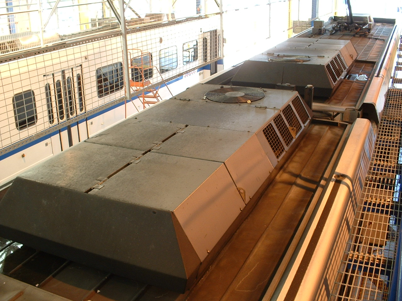 Picture 11-1 The two HVAC units on the roof
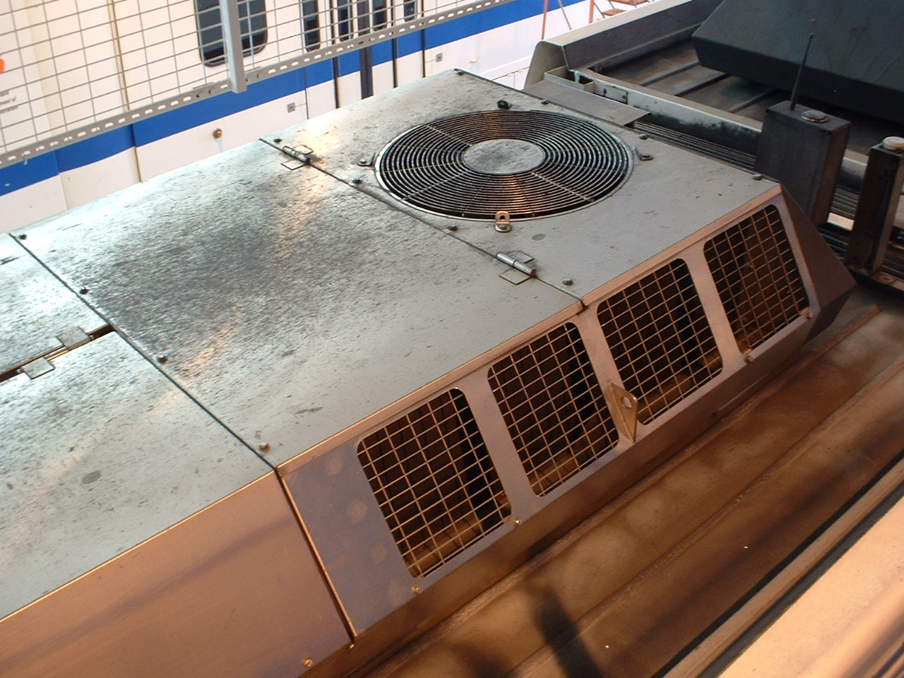 Picture 11-2 The cooling end of the unit
 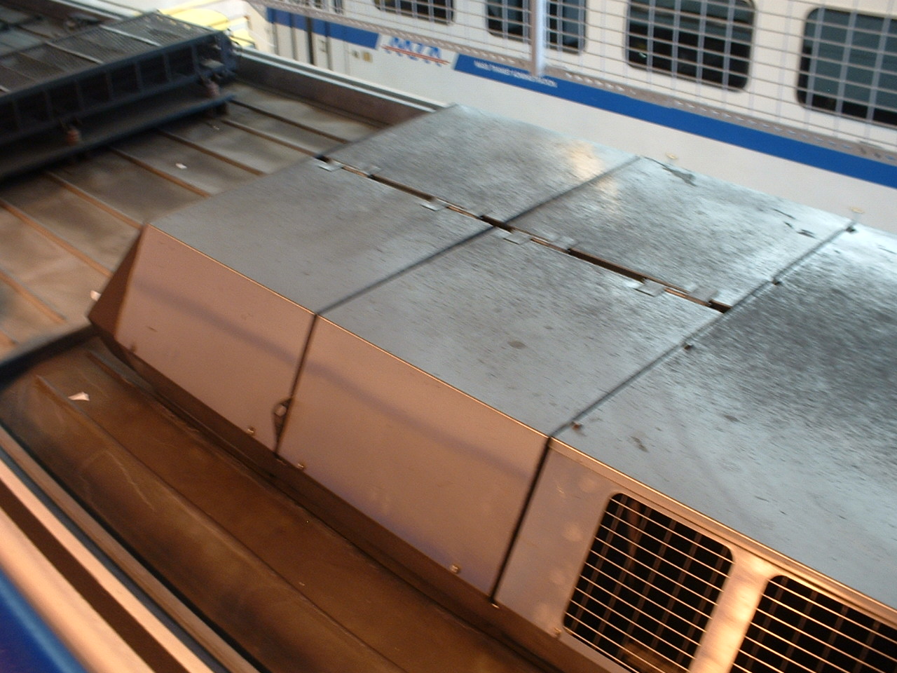 Picture 11-3 The heating and control end of the unit
 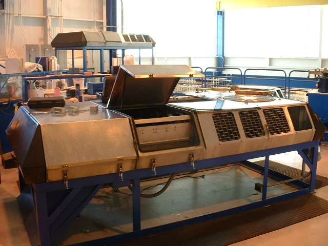 Picture 11-4 A HVAC unit in the maintenance shop
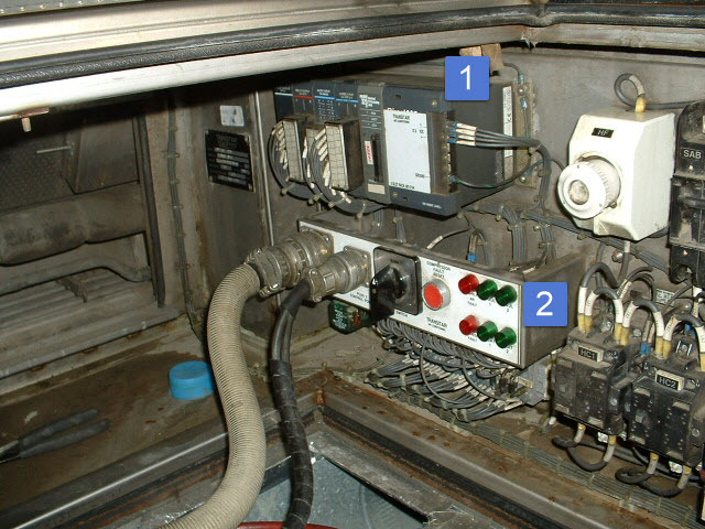 Picture 11-5 the PLC (1) and maintenance panel (2)
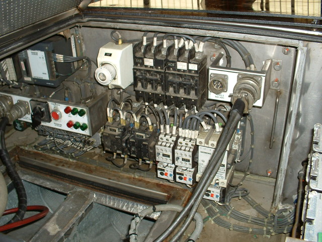 Picture 11-6 Remainder of the relays and controls
 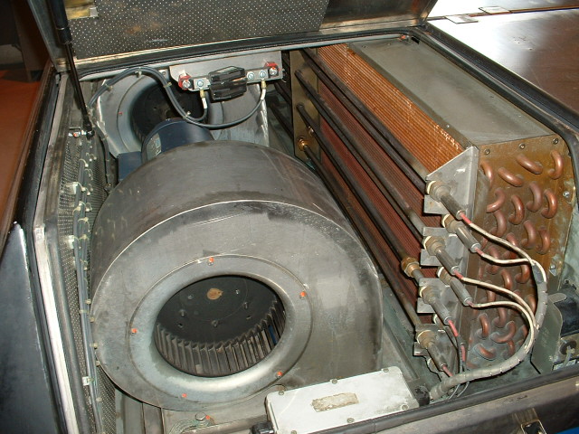 Picture 11-7 The heater elements and blower fan