CHAP 1 - Introduction CHAP 2 - Some Basic Specs CHAP 3 - Locations of Major Equipment CHAP 4 - the "TRACS" Computer System CHAP 5 - the High Voltage, Auxiliary and Propulsion Systems CHAP 6 - the Low Voltage Systems and Batteries CHAP 7 - the Air System CHAP 8 - the Braking System CHAP 9 - the Suspension System CHAP 10 - the Trucks CHAP 11 - the HVAC Units CHAP 12 - the PA and Intercom System CHAP 13 - the Pantographs CHAP 14 - the Doors CHAP 15 - the Couplers CHAP 16 - the Lighting System CHAP 17 - the Destination Signs CHAP 18 - Winterization CHAP 19 - Operation CHAP 20 - Maintenance CHAP 21 - Floobydust
12.1 The intercom/PA unit is located on the floor of the K91 locker. The unit is manufactured by COMCO, and has a standard FRA railroad connector and mount. Several functions
besides PA are handled by the unit. One is the bong it gives you when the car is auxed-on. Another bong is for stop requests, but it will only do it for the initial pushing of the switches.
Figure 12-1 Location of the K91 Locker.
Picture 12-1 The COMCO - PA/Intercom unit.
12.2 Inside the COMCO unit, there are four PC boards:
a) a motherboard,
b) a logic board,
c) a PA amplifier board, and
d) an intercom amplifier board.
12.3 Efforts have been
made on the bench to standardize the gain and level settings, but there is still a wide range of loudness levels from one car to the next, so there must be other factors involved.
12.4 For the PA function, the operator has two push button switches in the upper left corner of the center console, second row. One energizes the internal speakers (left), the
second from the left is for external speakers. There are five internal speakers in each section, and two external speakers in each section. So far, we haven't had any trouble with the speakers or the
microphones. The operators take fairly good care of the mics compared to the guys on the bus-side.
Picture 12-2 The center operators console
12.5 In the intercom mode, passengers can use one of three stations (COMCO calls them microphone plates) to talk to the operator. They do this by pressing a TALK REQUEST
button on the station. One of them is in the middle of the articulated section, and one is over each of the left handicap seats of each section. When one of the buttons is pushed, it will light
the intercom annunciator on the center console and bong the PA system. The operator responds by pressing the INTERCOM button and speaking. The second button (from the left)
on the top row is for the intercom. When he releases the button, the mic at the passenger station will be open till the operator presses the INTERCOM RESET button (third button from the left, top
row). Only the station that originated the request will hear the operator, unless more than one button was pushed. The station will still be enabled (a relay is latched "on"), even if
the car is keyed down. All of the lines going to the intercom station are in parallel except for the microphones, they are wired in series.
12.6 TECHNICAL SECTION:
12.7 For those of you that are a little more technically oriented, the COMCO unit still uses the good old 2N3055 power transistors in the output stage (won't they ever die?). The
amplifier design itself is fairly old, dating back to the 70's, and is a quasi-complementary symmetry design (same polarity output transistors, opposite polarity driver transistors). The amplifier for the
intercom is rated at around 13 watts, and the PA amp is rated at 25 watts. The only difference between the two, is that the PA amp uses two of the amplifier sections feeding into a push-pull output/matching
transformer. The speaker line through the car is a standard 70 volt distribution line. The external speakers are weatherproofed. The audio line drivers for the trainlines are basically the
driver stage of the amplifier. Drawing 12-1 is a block diagram of the COMCO unit and dwg 12-2 is an intercom amplifier.
12.8 There are two tone (or "bong") generators, one for the stop request and one for the intercom request. They are both generated from simple IC circuits. The
characteristic sound comes from a differentiating circuit that exponentially decays the output, giving it a distinctive sound. The intercom frequency is around 850 Hz and the stop request frequency is around
725 Hz. Drawing 12-3 is the intercom bong circuit.
12.9 Low noise op-amps (LM5534 types) are used for the low level audio amplification. CMOS 4066 type gates are used to switch the audio paths and to control the bongs.
12.10 The PA and intercom functions are trainlined, in sort of a master/slave relationship, so that an intercom request from one car goes through that cars COMCO unit, out over a train line,
and into the COMCO unit of the car the operator is in. There are 9 trainline signals for the COMCO unit:
a) intercom audio,
b) PA audio,
c) intercom reset,
d) external PA control (2 lines used as 1),
e) internal PA control,
f) stop request input, and
g) intercom request.
 NEXT Chapter ►
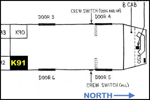 Figure 12-1 Location of the K91 Locker.
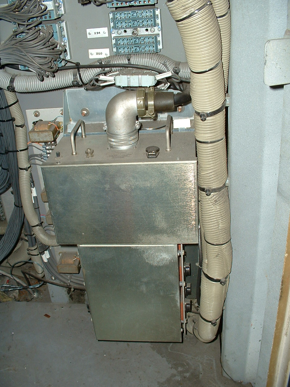 Picture 12-1 The COMCO - PA/Intercom unit.
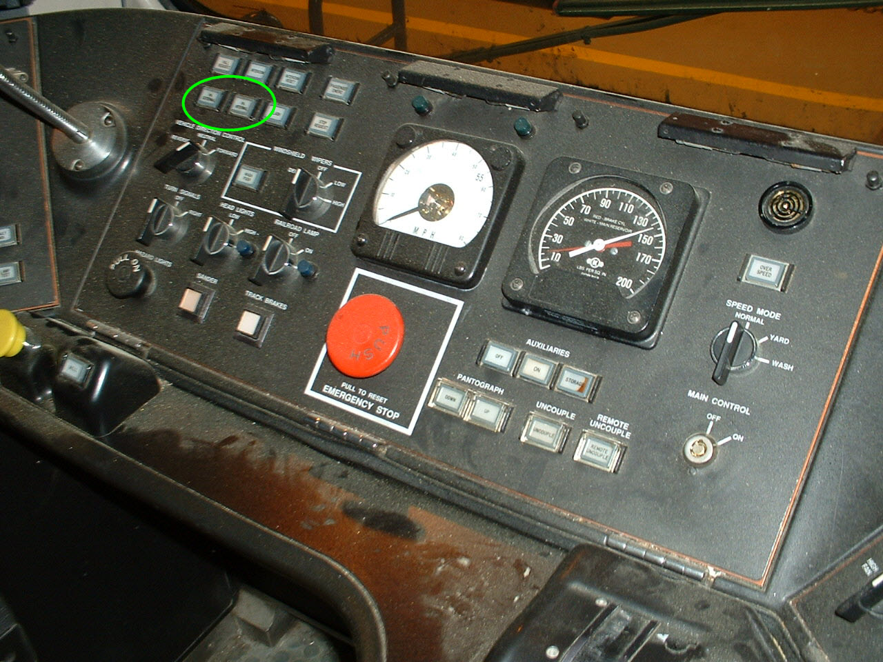 Picture 12-2 The center operators console