CHAP 1 - Introduction CHAP 2 - Some Basic Specs CHAP 3 - Locations of Major Equipment CHAP 4 - the "TRACS" Computer System CHAP 5 - the High Voltage, Auxiliary and Propulsion Systems
CHAP 6 - the Low Voltage Systems and Batteries CHAP 7 - the Air System CHAP 8 - the Braking System CHAP 9 - the Suspension System CHAP 10 - the Trucks CHAP 11 - the HVAC Units CHAP 12 - the PA and Intercom System CHAP 13 - the Pantographs CHAP 14 - the Doors CHAP 15 - the Couplers CHAP 16 - the Lighting System CHAP 17 - the Destination Signs CHAP 18 - Winterization CHAP 19 - Operation CHAP 20 - Maintenance CHAP 21 - Floobydust
6.1 The low-voltage system, is to say the least, different. Not too complicated, but there are a variety of voltages, which at times makes it difficult to
keep track of what is going on! As with the other sections, if you have access to the ABB drawings, the sheet numbers refer to pages in their manual of electrical drawings.
6.2 The battery charger is located in compartment B.U.U12, on the west side of the car and to the right of the aux module. It operates directly of off the 750V.
The only time it is not active, is when the pantograph is down. There is a 25A fuse (BA.FSBATCH) inline with the charger, located in the Q22 locker. The charger is capable of outputting 200A with the
train auxed-on, but is limited to 50A when auxed-off because of the lack of cooling air. There is an input to the charger which controls the charging rate, the line should be high to enable a high current
charging rate. This input goes to BP9 via two sets of contacts - one on the battery contactor (.21) (sheet 756/C) and one on the current relay for the converter internal blower (sht621/A). There are two
connections to the TRACS computer. One is the reset line, which originates from output 8 of board 3.161. Sometimes the charger will cease to function, and the computer will try to reset it. If that
fails to work, then the only other method of resetting the charger is by lowering and raising the pantograph. A set of relay contacts internal to the charger feed a signal to the TRACS computer. This
input tells the computer that the charger is working, and a corresponding LED is lit on the input module. Internally, the battery charger is really nothing more than a very big switching power supply,
converting the 750V down to 39V. See figure 5-1 (and sheet 701).
6.3 The output of the charger is labeled B+ and B-. The B- output is fed (within the U12 compartment), to a grounding bar. The B+ output feeds the battery
contactor and the BP5 circuits via the layover mode relay, .31 (dwg 6-1 and sheet 704). The only other
"circuits" powered directly from the charger is the battery pack and track brake circuit (sheet 702).
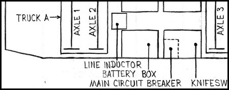
6.4 Juice to the batteries goes through a 250 amp circuit breaker. The CB is located to the left of the battery compartment, and is mainly used as a service disconnect, since I am unaware of any instance when the
breaker has blown. All of the low-voltage DC circuits go thru this breaker except for the track brakes.
6.5 Because of the high current demand of the six track brakes, they are directly connected the battery through a contactor mounted on the rear of the battery housing.
Now that ATC has been installed (2004 south end, 2005 north end), these track brake relays have been getting an overtime workout! :-)
Picture 6-1/6-2 Main circuit breaker and it's location
6.6 Items using the low-voltage DC voltage include:
The Headlight
The Railroad Lamp (used for the high beam)
The Radio / Comco unit
The operator control panel lights and lamps
The TRACS Computer
The Pantograph motors
The Coupler air solenoids
The Door Operators
The four emergency interior flourescent lights
The GPS Receivers
The VHF Radio
The Clearance Lights on the outside of the LRV
The overhead light in the operators cab
The Windshield Wipers
The Horn operating solenoid
The Track Brakes
The Destination Signs
The Windshield Wiper Heaters
6.7 Those of you who are familiar with batteries will ask why the Baltimore LRV's use 39V instead of the more standard 36V? MTA engineers chose to use a 39 volt battery
pack, because, it would allow for a slightly longer time operating off the batteries in the event of a battery charger failure or loss of high-voltage. Hopefully, if the batteries are in good condition, this
would allow the computer and emergency lights to operate for a round trip from Hunt Valley to Cromwell, without the need for rescuing. When the cars were new, this feature worked. Now that the cars have
15 years on them, it doesn’t. As a result, of course, a lot of 36V items don't like operating off of the higher voltage, the solenoids for the coupler 5x2 valves are one example.....special 40V coils had to be
specified and manufactured in order to keep them from burning up all the time! These were ordered and replaced in the 1996 time frame.
6.8 The batteries reside in a compartment on the east side of the train in the "A" section. They sit on a slide out shelf for ease of maintenance (one of
the few smart requirements the MTA engineers came up with). There are 21 cells, and are arranged in a (L to R) 4x4x4x4x5 order. They are nickel-cadmium batteries, with potassium hydroxide as the
electrolyte. Nominal cell voltage is 1.9 volts. No-one knows what the capacity of the battery pack is, and I have never seen any specifications for it.
6.9 The majority of the low-voltage DC breakers can be found in the K91 locker, which is in the “B”, or north section. Standing in the articulated section, and
looking north, it is the locker to your right. There are additional operator controlled circuit breakers located in each cab.
Picture 6-3 The low voltage CB's in the K91 locker.
6.10 In each cab, located to the right of the operator, and down below in the cabinet base, is a set of breakers for things like the headlight, railroad lamp, bell, horn, etc.
The operator would not normally have to do anything with these breakers unless they tripped for some reason (but then, that would normally signal a problems exists).
We'll talk about the alarm stuff at the top of the picture later.
Picture 6-4 Low voltage breakers for the headlights, bell, etc.
6.11 Over the left shoulder and behind the operator in each cab is a series of circuit breakers called "cutouts", several of which are low-voltage related for things like the
audible alarm cutout. All of these breakers have a seal on them, so railcar and operations will know if they have been defeated (which under normal circumstances is a no-no :-)
As you are standing in the aisle way of the car, they are located over the left cab window. The silver "thing" at the bottom of the picture is a flip out hanger for the operators coat.
 NEXT Chapter ►
 Picture 6-1/6-2 Main circuit breaker and it's location
 Picture 6-3 The low voltage CB's in the K91 locker.
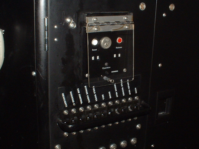 Picture 6-4 Low voltage breakers for the headlights, bell, etc.
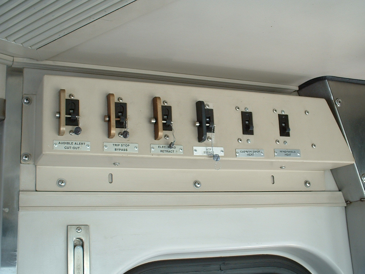 Picture 6-5 The cutout breakers in each cab.