CHAP 1 - Introduction CHAP 2 - Some Basic Specs CHAP 3 - Locations of Major Equipment CHAP 4 - the "TRACS" Computer System CHAP 5 - the High Voltage, Auxiliary and Propulsion Systems CHAP 6 - the Low Voltage Systems and Batteries CHAP 7 - the Air System CHAP 8 - the Braking System CHAP 9 - the Suspension System CHAP 10 - the Trucks CHAP 11 - the HVAC Units CHAP 12 - the PA and Intercom System CHAP 13 - the Pantographs CHAP 14 - the Doors CHAP 15 - the COUPLERS CHAP 16 - the Lighting System CHAP 17 - the Destination Signs CHAP 18 - Winterization CHAP 19 - Operation CHAP 20 - Maintenance CHAP 21 - Floobydust
15.1 As mentioned in chapter 2, the couplers are manufactured by Dellner. They are (probably) the most abused piece of gear on the cars. They are rated for a maximum coupling speed
of 5 MPH. Coupling much faster than that can damage the deformation tube. These are also one of the highest maintenance items on the car, which I don't
really understand because transit companies have been using automatic couplers since the early 1900's. The coupler design is unique to Dellner, so nothing else will mate to it. The couplers not only
provide a means of mechanically coupling the cars, but also provide the electrical and air connections too. This is accomplished by a pneumatically extended electrical head.
Picture 15-1 the Dellner Logo.
15.2 Picture 15-2 is a photo of the coupler, showing the main components. This is a photo I found on the internet, parts with a red "X" are not part of the Baltimore LRV
couplers, as this is a newer version. The main parts are:
(1) - the MRP Valve,
(2) - the Electrical Head,
(3) - the Locking Tang,
(4) - the Deformation Tube,
(5) - the Electrical Cables,
(6) - the Cushioning Cylinder
15.3 The air system on the coupler is pretty straightforward. There is a cutout for the coupler under the front of the car, just under the anti-climbers, to the right of the coupler
(it's labeled). It's a good idea to wear eye and ear protection when shutting off the air, because the air blast (from the relief port) is aimed at you. There is a direct 5/8" line going the
MRP valve on the face of the coupler. This valve is spring loaded, and when mated to another car, allows the air systems to be "paralleled. This comes in handy in the event of an air compressor
failure. The MRP valve can sometimes come unloose and rotate if the setscrews are not tight or are gone; make sure the dimples are at the 3 and 9 o'clock positions.
15.4; There is a "5 by 2" (5X2) valve located on the right side of the coupler (as you face the coupler end). This valve controls a pneumatic cylinder that extends and
retracts the electrical head. Early on we had trouble with the valves because the solenoid coils were rated for 36 volts and were burning up. Since replacing them with 40 volt coils, things have
been fine. The valves themselves tho, still go bad on a fairly regular basis due to the excess moisture that creeps into the system. Most of the time, it is the pilot valve orifices that get
clogged from corrosion. Also located at the bottom of the 5X2 valve, is another air “cut-out”, that releases pressure on the electrical head and centering device. Throwing it from the 9 o'clock
to the 6 o'clock position dumps the air. To replace the 5X2 valve, you need a 1/2" socket or wrench to remove the valve and cover, and a 9/16" wrench to take off the air lines. Sometimes, in
the winter, this valve can get frozen because of the moisture in the line. In this case, you have two options: 1) Cut the air out and manually extend and lock into place the electrical head (leaving the
air cutout), or 2) GENTLY heat the 5X2 valve with a propane torch to melt the ice build-up.
15.5 The centering device is a special pneumatic cylinder that puts the same air pressure on both sides of the piston to keep the coupler centered when not coupled to another car.
Coupling two cars on a curve requires that you cut the air out at the 5X2 valve, and manually align the two coupler faces before coupling-up.
15.6 The last air actuator on the coupler is the uncouple cylinder. This device allows the operator to uncouple cars from the cab. There are two buttons in each cab,
UNCOUPLE and REMOTE UNCOUPLE. Remote uncouple actuates the cylinder at the far end of the car, from where you are keyed-up). There is also a manual release cable on
the "right" side of the coupler.
15.7 Behind the face of the coupler near the top, is a microswitch. This switch actuates, through the key relays, the 5X2 valve, which in turn, supplies air to extend the
electrical head. The 5X2 actually reverses which side of the piston the air is on. Whenever you are playing around with the electrical head (and the microswitch), you have to be very careful,
IT COULD TAKE YOUR FINGERS OFF! When you push the UNCOUPLE button, and the couplers are still pushed together, you will probably get an X41 message on
the FIS, telling you that the microswitch is still pushed in. Once the cars are pulled away from each other, the message will disappear.
Figure 15-1 Basic coupler schematic
15.8 Let’s examine the coupler circuits in the “B” cab in more detail. The uncouple switch is AS.PBUNCBA (2). It is in parallel with the remote uncouple switch AS.PBUNCBB
(1) in the “A” cab (the “A” cab switches are AS.PBUNCAA and AS.PBUNCAB respectively). This command voltage then goes through zero speed relay TR.RL2ZERO (3), and directly activates the uncouple valve
AC.MVUNCB (4). It also energizes relay AS.RLUNCPLB (5), which is located in the K50 locker, under the operators console. When you push button (1) or (2), two contacts close and two contacts open
on this relay. The two contacts that close (6 and 14) energize the electrical head retract valve to disengage the electrical from the coupler of the other car.
15.8.1 As mentioned in 15.7, the “B” end microswitch ((12) and (13)) is AS.LSMECCOUPLB. This switch activates the 5X2 valve automatically, to extend and retract the electrical head when
cars are coupled and un-coupled. When cars are coupled, (12) will close and energize the extend valve (10) thru relay contact (7) and cut-out switch (8). When un-coupled, (13) will close, and
energize the retract valve (11) thru relay contact (15).
15.8.2 If for some reason, you do not want the electrical head of a car to mate with another, you can cut-out that function. There are two means at your disposal.
Paragraph 15.4 already discussed the manual way at the coupler by turning a valve to dump the air. The other method is by throwing a cut-out switch above and behind where the operator sits in the S44
cabinet. With the cut-out switch in the normal operate position, (8) is closed, and (9) is open. Throwing the switch reverses (8) and (9), opening the circuit to the extend valve so it is impossible
to energize that coil, and providing a continuous path to the retract coil, so that it remains energized all the time via (9) and (12) or (13) and (14).
15.9 The electrical head is responsible for transferring signals from one car to another. On each coupler, there are 60 movable and 60 non-movable contacts. The contacts are
numbered from the "outside" to the center, started with 1 on the top row for the left "movable" contacts, and 101 on the right section of "fixed" contacts. Most of the contact
functions are mirrored, in other words, the PAN UP signal appears on both pins 4 and 104. The electrical head also serves the purpose of a junction box for the wiring on the couplers, since
all of the electrical commands come through the "left" cable. Generally, the "left" cable is for power and 39 volt level signals. The "right" cable is
mainly for the low-level and signal lines, such as the PA/IC audio signals and the TRACS ITDC line. Changing out the electrical head is a pain in the ass.
15.10 The electrical head has also been a constant source of problems for the MTA. At the rear of the head, there are two "horns". These horns have mil-spec connectors
at the bottom end of them. Cables connect to these connectors, and go to a junction box mounted under the floor of the cab, just above the coupler. We have experienced problems like you wouldn't believe
with the horns and cables due to water damage. Moisture is somehow finding its way into the electrical head, and likes to settle in the lowest place, mainly the backside of the mil-spec connectors. Over
a period of time, the wires and pins corrode and turn green, and create some very strange problems on the cars. Water has also gotten into the cables and done the same thing. I had suggested the use
of silicone grease (or potting) a long time ago to help seal out moisture, "but the foremen know better", so we still have problems. The cable problem has been supposedly fixed by Dellner coming
in and building all new cables, with improved connector to outside sheath mating, hopefully eliminating water seepage. The moisture problem inside the electrical head has been addressed, but no real solution
has been undertaken. One other water problem that has gone unaddressed, is the water seepage that occurs between the screw-on mating surfaces of the two connectors. Since the "male" connector
is on top, water comes down between the pieces on the threads and corrodes the pins. When I worked there, I had suggested putting silicone grease or "anti-seize" compound on the threads to eliminate
water seepage to no avail because again, the management knows better!
15.11 During inclement weather, when there is the possibility of snow or ice, the operator can turn on the coupler heat, via circuit breaker CM.CBHEACPLx in the K50 locker. The breakers
are fed by the lay-over-supply, LOS, and the circuit becomes BP27A and BP27B after passing thru the CB. In addition, for the past 10+ years, railcar has been bagging the couplers – placing a trash bag over the
entire coupler end to protest the electrical head and mechanical components from getting any accumulation on them. Coupler heat is not used when the couplers are bagged.
15.12 The coupler is supported by a leaf spring. There are two special (3/4") bolts holding the leaf spring in place, which are used to adjust the height of the coupler. The
coupler height is adjusted by first loosening the locknuts on the top of the leaf spring clamp assembly. Then the bolts are adjusted in or out to bring the height into spec. There is a fixture floating
around, painted yellow, that rests across the two rails and has a vertical scale on it. The scale shows where the center should be and also has two lines for the limits of adjustment. After adjusting
the bolts, you should press down and release the coupler to see where it returns. It should rest between the limit marks. On the coupler face, smack dab in the middle, you should find a little dimple.
This is the point you should be aligning the height adjustment to. After you’re done, re-tighten the locknut. There is a lot of weight on these two bolts, and periodically they do
break, so its something to look for on weekly inspections. Also on the leaf spring, there is another clamp/bracket. The bolts on these guys also snap once and a while.
15.13 Also in figure 15-1, is a guide to the lubrication points and the types of grease that should be used. Greasing is done every 45 days in normal service. Once a week,
the coupler faces are lightly "sanded" and sprayed with a lubricant, and, the main electrical head pins are checked for pitting and/or damage and cleaned. Bad ones are easy to replace with an 8mm
nut driver.
 NEXT Chapter ►
 Picture 15-1 the Dellner Logo.
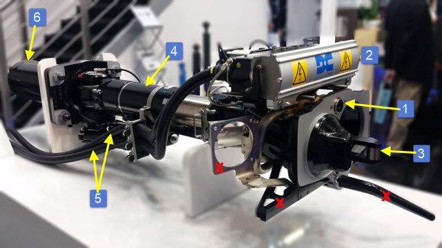
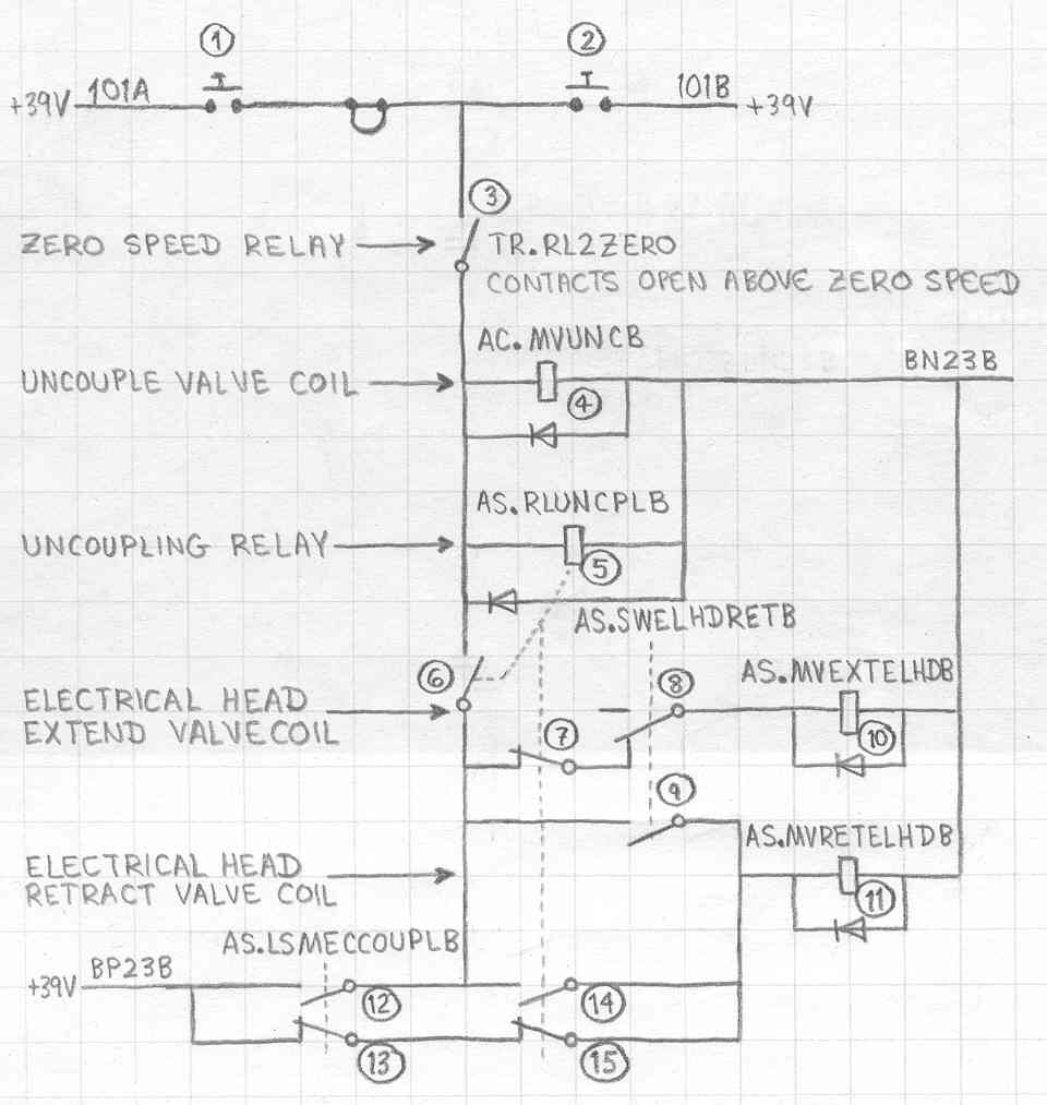 Figure 15-1 Basic coupler schematic