CHAP 1 - Introduction CHAP 2 - Some Basic Specs CHAP 3 - Locations of Major Equipment CHAP 4 - the "TRACS" Computer System CHAP 5 - the High Voltage, Auxiliary and Propulsion Systems CHAP 6 - the Low Voltage Systems and Batteries CHAP 7 - the Air System CHAP 8 - the Braking System CHAP 9 - the Suspension System CHAP 10 - the Trucks CHAP 11 - the HVAC Units CHAP 12 - the PA and Intercom System CHAP 13 - the Pantographs CHAP 14 - the Doors CHAP 15 - the Couplers CHAP 16 - the Lighting System CHAP 17 - the Destination Signs CHAP 18 - Winterization CHAP 19 - Operation CHAP 20 - Maintenance CHAP 21 - Floobydust
13.1 Originally, the pantographs are located on the "A" end of the car, with the exception of cars 31-35, which have an additional pantograph on the "B" end for the purpose
of ice removal. The original pantographs and replacements were designed by Stemmann-Technik GmBH (Germany) and supplied by Transtech.
Replacements originally cost $20K. Then came along replacements designed by Shunk and manufactured by UKM for around $16K.
Transtech countered by lowering their price to $15K, and then UKM to $14K (that still seems like a lot - compared to a trolley pole). The Shunks are also the OEM pans on the new cars.
13.2 The pantographs are adjusted for 19/+2/-0 pounds of tension (or upward push), which I have heard is on the heavy side.
13.3 After several bad winters, the MTA decided to experiment with several ice removal systems - after having many, many stranded trains and many, many pissed off customers. One of the
first solutions was to create an ice train. This consisted of three cars that were "semi-permanently" coupled together for the duration of the winter
season. The middle car had an ice scraper pan head installed. The two end cars had their pantographs electrically connected by means of two large cables running across the roof tops. This was
(supposedly) to prevent the train from getting stuck on a section of the catenary that was covered with ice (yea, right).
13.4.1 Before the winter season of 96-97 set in, cars 31-35 had a second pantograph installed, so they could assume the roll of the ice trains. This required the relocation of the braking
resistor and strengthening of the roof. The second pan is electrically isolated , in other words, it does not connect to anything electrically. A circuit breaker (CB) located next to the windshield
heat CB in the cab raises and lowers the pan. These pans have a grooved brass contact surface, supposedly designed to scrape ice off the wire. They’ve had limited success with them. Watching a
train going down the track when the lines are icing is something to behold, especially if at night – you can see a train coming and going for miles. Operations is so scared of bad weather now, that they send
these ice trains out when the temperature gets down to 40, even with clear skies.
13.4.2 In the late 90’s, the remainder of the fleet had the second pan added.
13.4.3 Case in point.... the other week, back in January of 2012 on the way to a train show held at the fairgrounds in Timonium (which is next to the light rail tracks), I had to cross the
tracks to get there. As I approached the crossing, the gates were going up and down, with about 10 seconds in between the attempts to go down. As I crossed the tracks, off to my right, was an LRV,
stopped dead in the tracks. It had snowed and rained the night before, and frozen pretty good. The train was stuck.... So much for the scraper pans!
13.5 During the warmer months, the cars operate with standard collector shoes. Around October, we begin to put on shoes that have a heater strip
mounted on them. They operate directly off the 750V wire, using a contactor located near the base of the pan to complete the circuit to ground through a 25 Amp fuse. A little overkill considering they
only draw about 1 amp. A CB in the cutout box of the "A" end turns the heater strips on n off. Because they are operated from the 750V, they become useless once they hit an ice patch,
especially since they have very little thermal mass to cut through any substantial amount of ice.
13.6 Maybe you have seen them, and wondered why the ends of the horns are painted white. This is so we can tell if the catenary wire has come down too far, indicating a potentially
dangerous situation if the wire were to come down over the end of the horn (which means the pantograph could extend all the way up and get ripped off or otherwise seriously damaged).
Picture 13-1 The white horns
13.7 The pantographs normally get inspected once a week as part of the weekly inspection. We check the condition of the carbon contact strip; the upward pressure, both up high next to
the catenary wire, and in the retracted position; the jumpers; the wires; and look for evidence of the white paint being scraped off. Any discrepancies are noted on the weekly inspection list, and get
corrected. If the paint is scraped off the horns, we are also supposed to notify the foreman, so they can contact the overhead department.
13.8 The following pictures show the various parts of the pantograph.
Picture 13-2 Top half of the pantograph
Picture 13-3 Another shot of the top of the pantograph
Picture 13-4 The lower half of the pantograph
13.9 The pantograph is mounted to the roof via a set of insulators... remember that the pantograph is "hot" compared to the body of the LRV, nominally 750VDC. The pantograph
can even be hot in the event that the pantograph is down, if the car is plugged into shop power.
13.10 A small motor provides the pull to lower and raise the pantograph. The motor can be seen above the frame at the bottom of picture 13-5.
Picture 13-5 The springs that keep the pantograph "up"
Picture 13-6 Connection of the springs to the pantograph
Picture 13-7 The pantograph base
13.11.1 The operator has two controls for the pantograph, one to lower it, and one to raise it. Since the pantograph motors are 39 volt motors, the buttons work even when the train
is AUXED OFF. Otherwise, how would you raise the pans if you didn't have 750VDC? The DOWN button only works if the train is at a full stop, and you are KEYED DOWN.
13.11.2 In the event that you have lost battery power, or the pan motor is otherwise disabled or broken, the pantograph can be raised manually. In the cab, there is a crank with about
a three foot long fiberglass rod attached to it, that allows the operator or maintenance personnel to crank the pan. If you look inside the LRV, underneath where the pan is, you will see a small hole
about 5/8" inch in diameter... this is where the crank it put through the ceiling of the car to engage a mating shaft on the bottom of the motor housing. The crank is mounted on the end of a
fiberglass rod to insulate you from the 750 volts.
Picture 13-8 Operator controls for (among other things) the pantograph
13.11 Pantographs are maintained in a shop located on the mezzanine. When they are removed and replaced, the LRV's are shoved up onto track 1N, where there is no catenary to
get in the way. You will notice a small "D-Ring" on each corner of the pantograph base, this is where lines are attached to lift them off the car using an overhead crane, the same one
used to remove the HVAC units. If shop power is needed, there is a connection nearby.
 NEXT Chapter ►
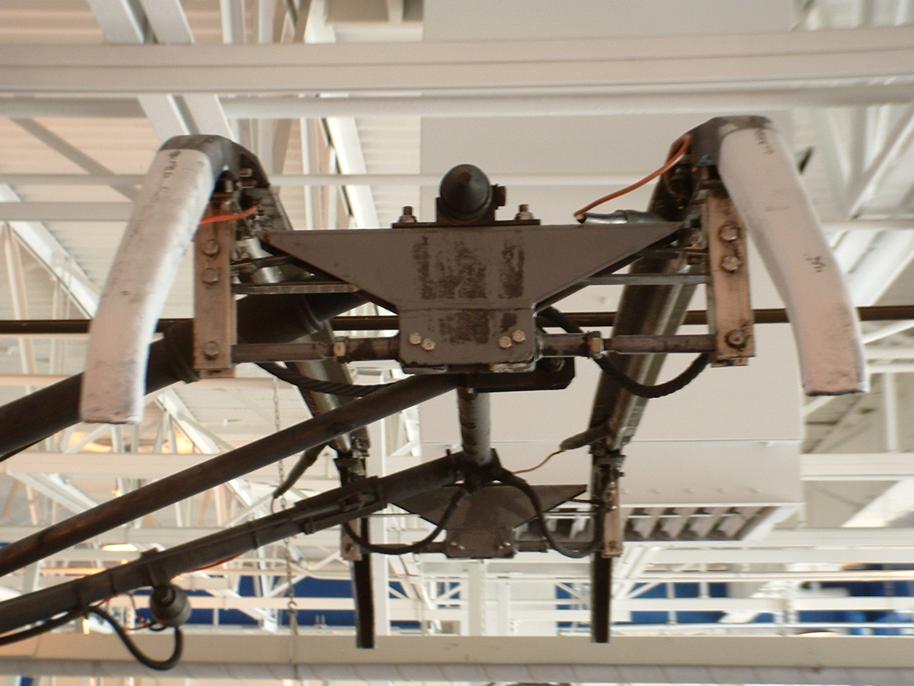 Picture 13-1 The white horns
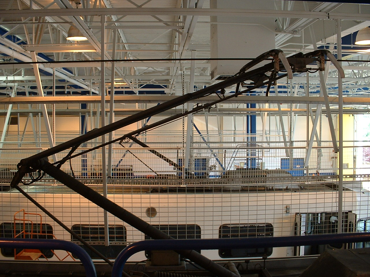 Picture 13-2 Top half of the pantograph
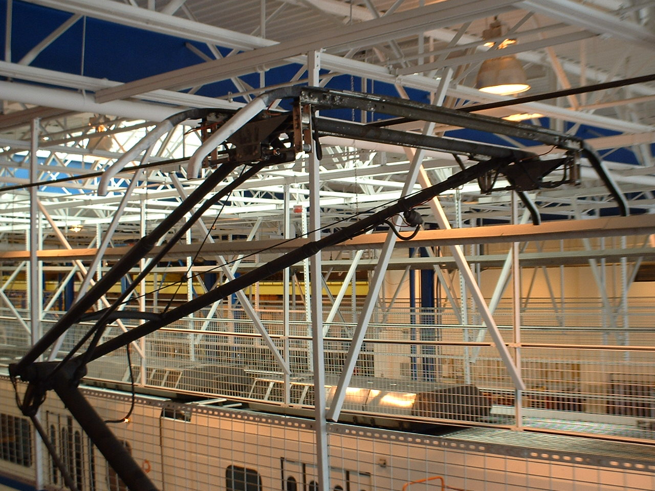 Picture 13-3 Another shot of the top of the pantograph
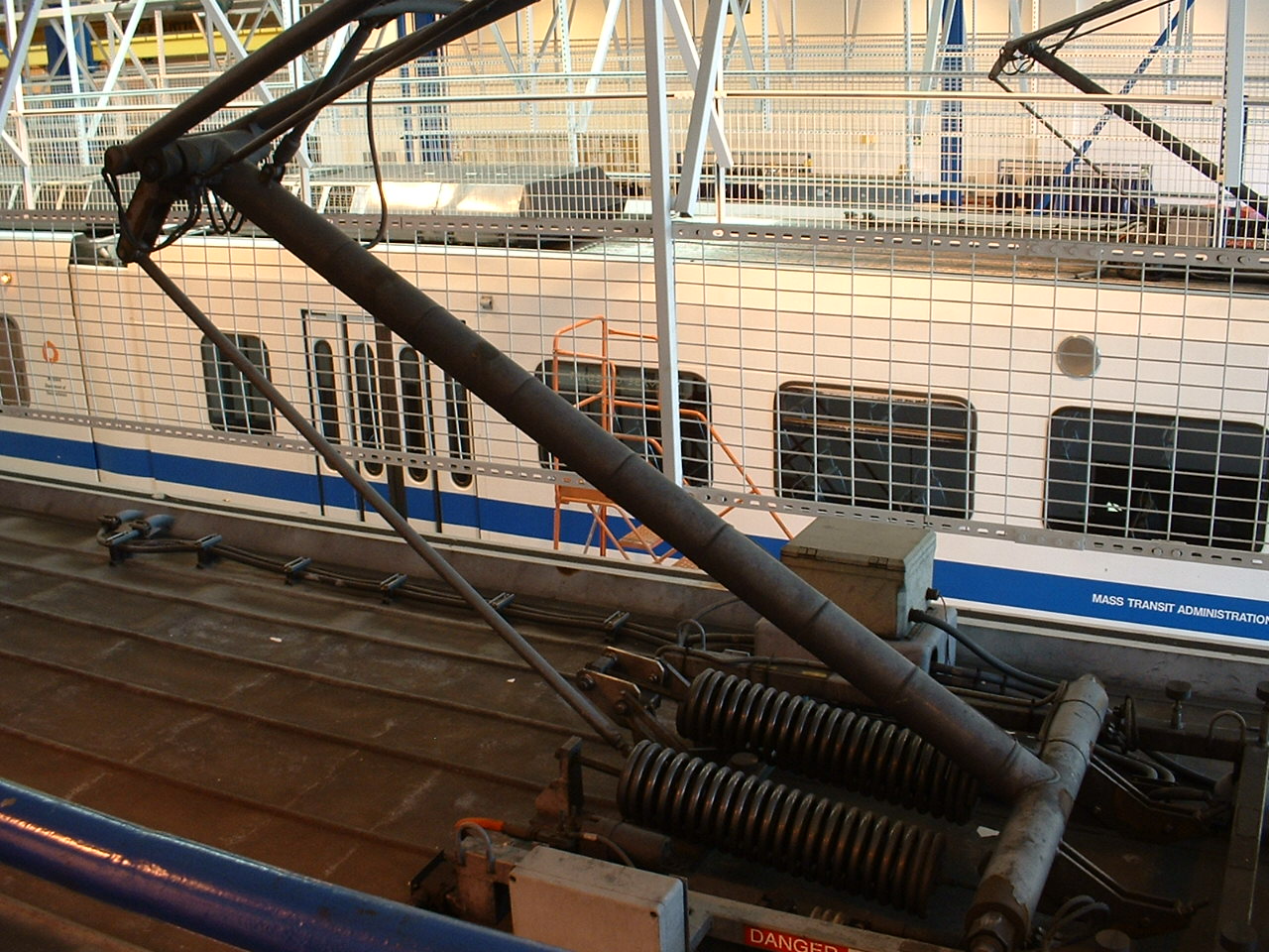 Picture 13-4 The lower half of the pantograph
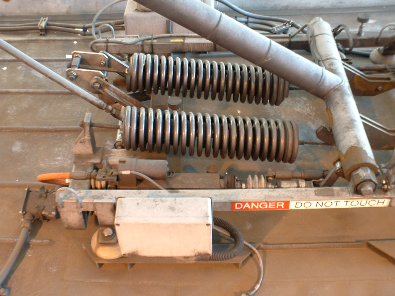 Picture 13-5 The springs that keep the pantograph "up"
 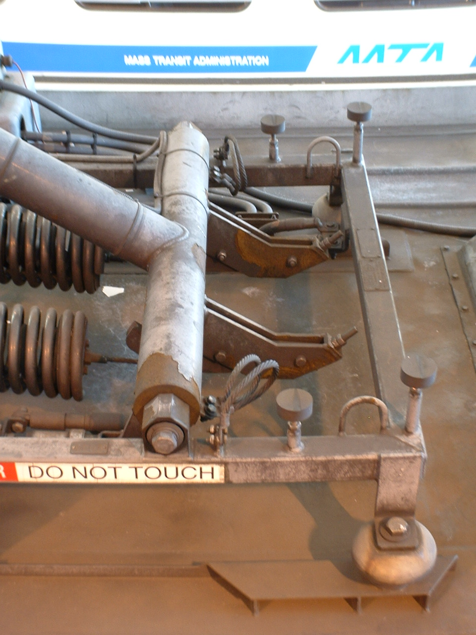 Picture 13-6 Connection of the springs to the pantograph
 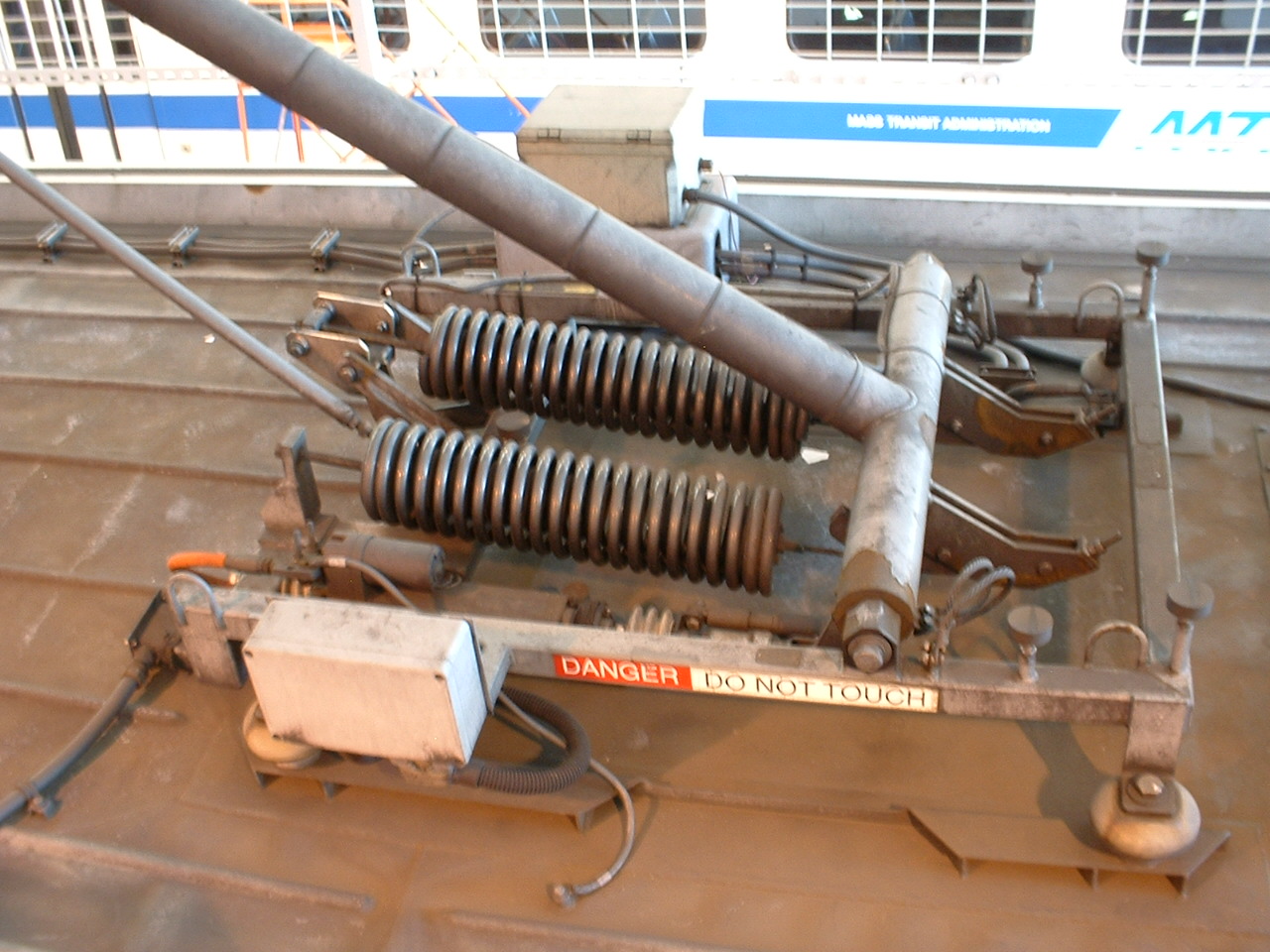 Picture 13-7 The pantograph base
 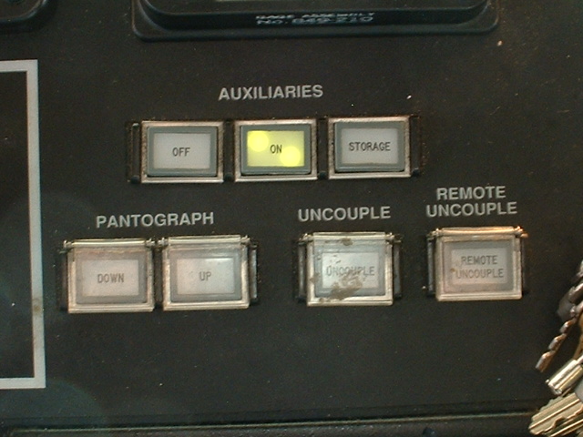 Picture 13-8 Operator controls for (among other things) the pantograph