CHAP 1 - Introduction CHAP 2 - Some Basic Specs CHAP 3 - Locations of Major Equipment CHAP 4 - the "TRACS" Computer System CHAP 5 - the High Voltage, Auxiliary and Propulsion Systems CHAP 6 - the Low Voltage Systems and Batteries CHAP 7 - the Air System CHAP 8 - the Braking System CHAP 9 - the Suspension System CHAP 10 - the Trucks CHAP 11 - the HVAC Units CHAP 12 - the PA and Intercom System CHAP 13 - the Pantographs CHAP 14 - the DOORS and CHASSIS CHAP 15 - the Couplers CHAP 16 - the Lighting System CHAP 17 - the Destination Signs CHAP 18 - Winterization CHAP 19 - Operation CHAP 20 - Maintenance CHAP 21 - Floobydust
14.1 Yes, there are doors, eight in each car to be exact. Door number one is to the right of the "A" cab, and door number eight is to the left. They are sort of numbered
like the pins on an IC, down one side, cross over, and then numbered back up to the original end. Figure 14-1 makes sense out of what I just said.
Figure 14-1 Door Locations.
14.2 The operator controls the doors from two sets of switches on the left and right consoles in each cab. The "left" and "right" designations change sides when you
change cabs. In other words, the left side from cab "A", is the right side from cab "B". This also affects the coupler pin assignments, so be extra careful when tracing out the
trainline circuits from the couplers. What goes on in the door circuits is complicated, but not unmanageable. It may take several readings to understand the operation of a particular function,
complicated mostly from all of the safety interlocks. Referring to figure 14-1 a lot will help get you through. There is no straightforward way to explain what goes on because of the way the
circuits are tied into one another.
Picture 14-1 The Door Operator.
14.3 Door control is independent of the computer. There are inputs to the computer from the door system, however. For instance, if the doors are open, it will prohibit propulsion and
keep the cars brakes on (If you have already gone through the computer section, you know of an exception to this). Also, if one of the doors is cut out, the computer knows this and puts a message on the
FIS. Sometime after the double tracking in 2005, the MTA engineers decided things weren't complicated enough, and added a PLC to each door operator, violating the KISS principle - I don't have any details
of its function or operation..... yet.
14.4 The relay logic for the doors is on the back of the K91 circuit breaker panel door). These relays, so far, have been very reliable. The operator controls in each cab go to this
panel. Over each door is a door operator (picture 14-1). This assembly contains:
1) a pressure regulator,
2) the engine (air cylinder) and actuating valve,
3) a locking pawl
4) locking pawl solenoid,
5) limit switches,
6) a timer relay,
7) a test jack,
8) emergency cutout,
9) door out of service cutout,
10) sensitive edge switches,
11) air shut-off (turn this off, and there is no air to the door operator)
14.4.1 The wiring diagram manual covers the door circuits in the 1100 series. Figure 14-2 is a circuit diagram for door 1.
14.5 There are three basic modes of operation for the doors: 1) OPEN, 2) RELEASE, and 3) CLOSE, further modified by the position of the selector switch for
1) ALL, 2) FRONT, or 3) REAR.
Picture 14-2 Control for the right side doors
14.6 Pushing the OPEN button will open the doors on either the left or right side. The doors opened are controlled by the selector switch. ALL opens just
that, all four doors of a side. FRONT will open ONLY the door just to the left or right of the operator (used for handicap access and when operators get on and off at the relief point).
REAR opens all of the doors except the ones adjacent to the operator. This is how the cars are usually run, for the hi-blocks are usually down and they don't want those doors to open. In a multiple car
consist, all eight doors of the any additional cars will operate as part of the ALL or REAR mode.
14.7 The next few paragraphs refer to picture 14-3.
14.8 The RELEASE button ENABLES the doors to be opened (it's sort of like putting the doors in a "local control" mode). Operators usually put the doors in this mode
when in a station. This allows only the doors, where passengers are boarding or getting off, to open - thereby saving on cooling or heating. When the doors are put in release, the locking pawls (2) of
each door operator are lifted, and the door push buttons become illuminated. By pressing one of the buttons from either the inside or outside, the door will open. The solenoid
(1) that releases the pawls are at the bottom of the photo, and you can see it pushing a lever with a nylon latching piece (2) on the end of it.
14.9 The Sonalert (8) is shown in picture 14-3, it's over to the left. This sounds off when the doors are about to close.
14.10 Also shown in picture 14-3, is the gear (4) that drives the two connecting rods (6) to open and close the door. The rods are attached to the notched swashplate (3), that the nylon
pawl is in. The gear engages with a flat toothed bar that is between the two "engines" (or pneumatic cylinders) - one opens the doors, the other one closes them. The end of one of the engines
can be seen at 5. When the doors are in "release", the switch (7) reports back to the TRACS computer, and lights up the release lamp on the control panel.
Picture 14-3 Release mechanism
14.11 In the picture below, you can clearly see the control valve (1), and the right engine (2). On the right side of the engine are the adjustments to control the open and close rates
(3). The control valve has two "dimples", or recessed manual controls to activate the valve in lieu of an electrical command that operates the solenoid to pull the valve one way or another
(they can't be seen in this photo). This allows the ET's to check the engine without having someone press the buttons in the cab. Also shown in the photo is a pressure sensor (4) which reports to
the TRACS computer if is there is insufficient air to operate the mechanism.
Picture 14-4 Control valve and right engine
14.12 Picture 14-5 illustrates the timer relay (1), the right sensitive edge pressure switch (2), the test connector (3), and the wiring terminal strips (4). You can also see the upper
door mount (5), with the connecting rod on top (6).
Picture 14-5 Stuff on the right side of the door operator
14.13 In photo 14-6, we can see the two switches which tell the TRACS computer that the doors are closed. They are not inherently failsafe. If these switches go bad, the train cannot move.
Picture 14-6 Door closed switches
14.14 Continuing with the circuit description..... By pressing the CLOSE(D) button, a command will be issued to all of the doors, regardless of the position of the selector switch.
This command takes the doors out of release (if in that mode), sets off the sonalerts to alert the passengers, and energizes the air valve (DCLV) to close the doors. The close door function takes a perverted
path through the door circuits, so don't feel bad if it's not readily apparent as to what's going on.
14.15 While the train is moving, the only thing that can happen with the doors is to use the interior door stanchion buttons or tape switches to signal the operator you want to get off (this
is a stop request - covered in the intercom/pa section). The zero speed relay prevents the door circuits from operating till the speed drops below the zero speed point.
14.16 For any of the door controls to work, a cab has to be keyed-up. There are four sets of contacts on the key relays for each end. One set enables the left operator controls, the
other set is inline with the left door closed summary lamp in the CLOSE(D) push button. These two sets of contacts are duplicated for the right side. Power for the door controls originates
from CB5 - Door power. It then goes through a set of contacts on the zero speed relay, that prevents the doors from being opened above 1.5mph. Power then goes through a key relay, to the push button
switches on the left and right consoles. One of the door open lines also goes through the mode selector switches.
14.17 When the operator pushes the RELEASE button, two signals are sent out over trainlines: 1) passenger enable and 2) door unlock/release. These control signals are isolated
from the trainline by a diode (the trainline signals are an active high (39VDC)). The passenger enable trainline energizes relays PER and PESR. The relays are additionally isolated from the trainline
by a diode, and also has to go through a set of contacts on the DCR relay which prevents the doors from being put into release until the doors are closed. The function is latching through a set of contacts
on the PESR relay, which keeps them energized once the RELEASE button has been released (hence the need for the isolation diode). The door unlock/release trainline energizes the DUR and DUSR relays
(going through another set of DCR contacts). This function is also latching. When these relays are pulled in, they illuminate the lamps in the exterior and interior door open push button switches and
energize the DLS, or door latch solenoid. This solenoid pulls the locking pawl up so the doors can be opened. (The lamps and circuits for doors 1, 4, 5, and 8 also go through the FRONT/ALL/REAR
switch - If the operator is in the "A" cab, and has the selector switch in the REAR position, doors 1 and 8 will not light up or be enabled.) When someone pushes one of the door switches, the DCLV
is thrown into the OPEN position, and sends air to the door engine, opening the door. Between the switch and the DCLV, are the two crew switches, a NC cut-out switch contact, and an SLS lock switch
contact. The release function does not work if the selector switch is in the FRONT position.
14.18 If the OPEN switch is pushed, two control signals are sent out over the trainlines: 1) Door unlock/release, and 2) Door open (this is the line that goes through the selector
switch - this signal goes out over the trainline only in the ALL and REAR positions, otherwise, the command goes directly to the "open side" of the DCLV valve). Going on, with the DUR and DOR
relays energized, the BP5 path passes around the door open PB switches and goes thru the crew switch to energize the SLS and the "open" side of the DCLV. Simple, isn't it?
14.19 Finally, when the CLOSE(D) button is pushed, it creates terror in the eyes of the repair technician (just kidding). The signal goes through a diode to the DOOR CLOSE/LOCK
trainline. On the door panel, it goes through a set of contacts of the TDR2 relay and into the TDR1 relay. TDR1 energizes for a period of around 3 seconds, and TDR2 has a time delay of about 2 seconds
before it becomes energized.
14.20 Each door has a Sonalert in the door operator (see picture 14-3). This goes off for about 2 seconds after the operator has pushed the CLOSE(D) button. Following along on
the right side of the drawing, power comes off the BP5 line through the C1 set of TDR2 contacts (which are closed). Then through the C2 contacts of TDR1. These contacts are open until the relay is
energized when door close trainline goes high. The contacts will stay closed for the duration of the TDR1 timing cycle, about 3 seconds.
14.21 On each bi-fold door edge, there is a sensitive edge. These sensitive edges detect when someone is still in the doorway if the doors are
in the process of closing. Inside the rubber edge is an airtight tubular channel, connected to a small hose. The hose snakes its way through the door, comes out through the upper door hinge and then
goes to a pressure switch. It's called the SES, or, sensitive edge switch. During the weekly inspection, the doors are checked to make sure that the doors will open if a 2" block of wood (or similar
2" object) is placed in the doorway, and close with a 1" object. Once a close door command has been issued, it will energize the SEER relay (sensitive edge enable relay - I know, saying relay after
SEER is redundant, oh well), once the doors have started closing and an LS1 contact closes. The SEER relay will enable the SES circuit. An LS2 contact opens the circuit once the doors are within an inch
or so of closing (that's why we check with a 1" object). If one of the SES switches is closed, it triggers the SER time delay relay. Contact C2 flips and provides the DCLV with an open command.
The amount of delay should be around 3.5 seconds (it's adjustable). Once the door has fully opened, the close door command (it's still there) will make the doors close once again. This process will go on
till the obstruction in the doorway is cleared.
Picture 14-7 Pressure
regulator (1), sensitive edge sensor (2), air shut-off (3), door operating crank
(4)
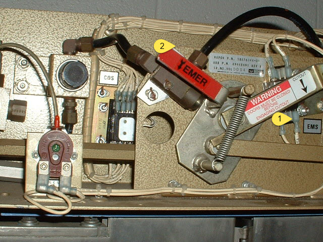
14.22 When the doors are cut-out, the doors can not be opened. A handle in the right door operator assembly puts the doors into cut-out
(See picture 14-8). When pulled down, it opens up various circuits, thereby prohibiting the doors from being opened. A pair of pins is also dropped down into the doors to prevent them from being
forced open. There are six set of contacts associated with doors being cut-out. One set bypasses the contacts in the door closed summary circuit except for the emergency switch. Another set
turns on the "door out of service" light over the door. Another set signals the TRACS computer. Another set opens the BP5 line. The DCLV valve (open side) is shut off by another
set. The last set opens the door close command line.
Picture 14-8 Manual cutout
(1) and emergency valves (2)
14.23 In an emergency, the doors can be opened manually by two methods. A plastic window, or frangible shield as they are called, is broken to
gain access to an emergency handle. Pulling this handle pulls on the emergency handle assembly on the door operator. Doors 1 and 5 also have a manual release cable on the outside, located under the
skirt to the left of the door. The other way is to open the access panel above the door, and pull the RED handle down. This releases (or "dumps") the air out of the doors' pneumatic system,
pulls the locking pawl up, and releases the door so it can be opened. A set of contacts (labeled EMS) in the door closed summary circuit opens up to prevent propulsion. A second set of contacts energizes
the PASSENGER EMERGENCY trainline, which lights an annunciator on the center console of the cab. See picture 14-8.
14.24 There are a number of adjustments to be made to the doors. As you look at the large end of the engine, there are three adjustment screws, two at the top and one to your left. Of the
two at the top, the left one controls the door closing rate. The right one controls the door opening rate, but interacts with the control on the left, which is the "cushion" adjustment. On an
annual basis, the air lines to both sides of the engine should be taken off, and 2 or 3 squirts of oil should be put in both sides of the engine. The connecting rod from the teetering plate to the lever may
require adjustment once and awhile. Make sure the doors are closed and the locking pawl is down. There are two "inspection holes" in the connecting rod ends. After adjustment, make sure
a piece of wire inserted in these holes hits the connecting rods, if not, the rods must be readjusted. Switches LS1 and LS2 may needed adjustment is the doors don't respond properly to opening and closing
specs. They are mounted on swash plates, which can be moved by loosening two screws, although the screws are hard to get to and you need an offset screwdriver.
14.25 There are two ways to get into a closed car. The normal method is to use one of the crew switches, located to the left of doors 1 and 5. On the new cars (5036 and
up), additional switches were added to the right of doors 4 and 8. The crew switch circuit is one of the few circuits still energized when the car is in lay over mode. If the batteries are weak or
if there is no air, you can pull one of the external door releases. The releases are located to the left of doors 1 and five under the "little" skirt. Pulling the handle will pull on the
emergency cutout in the door operator and release the door. Sometimes these are hard to operate, and you may have to get someone else to push on the door as you pull on the cable. Once the door has
been released, there are "hand holds" recessed into the door that allow you to pull the door open.
14.26 Below are two pictures of the door test stand we made for use around the shop in case we need to see if something works, or for use in the doors class.
 NEXT Chapter ►
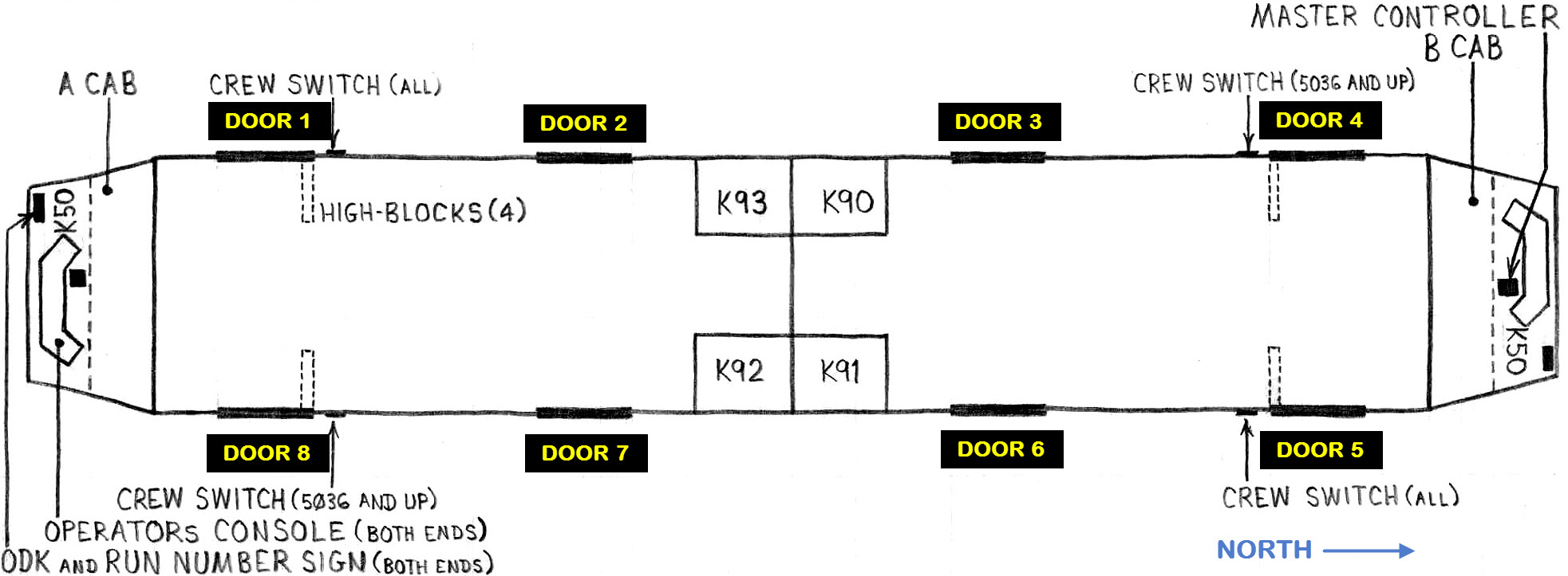 Figure 14-1 Door Locations.
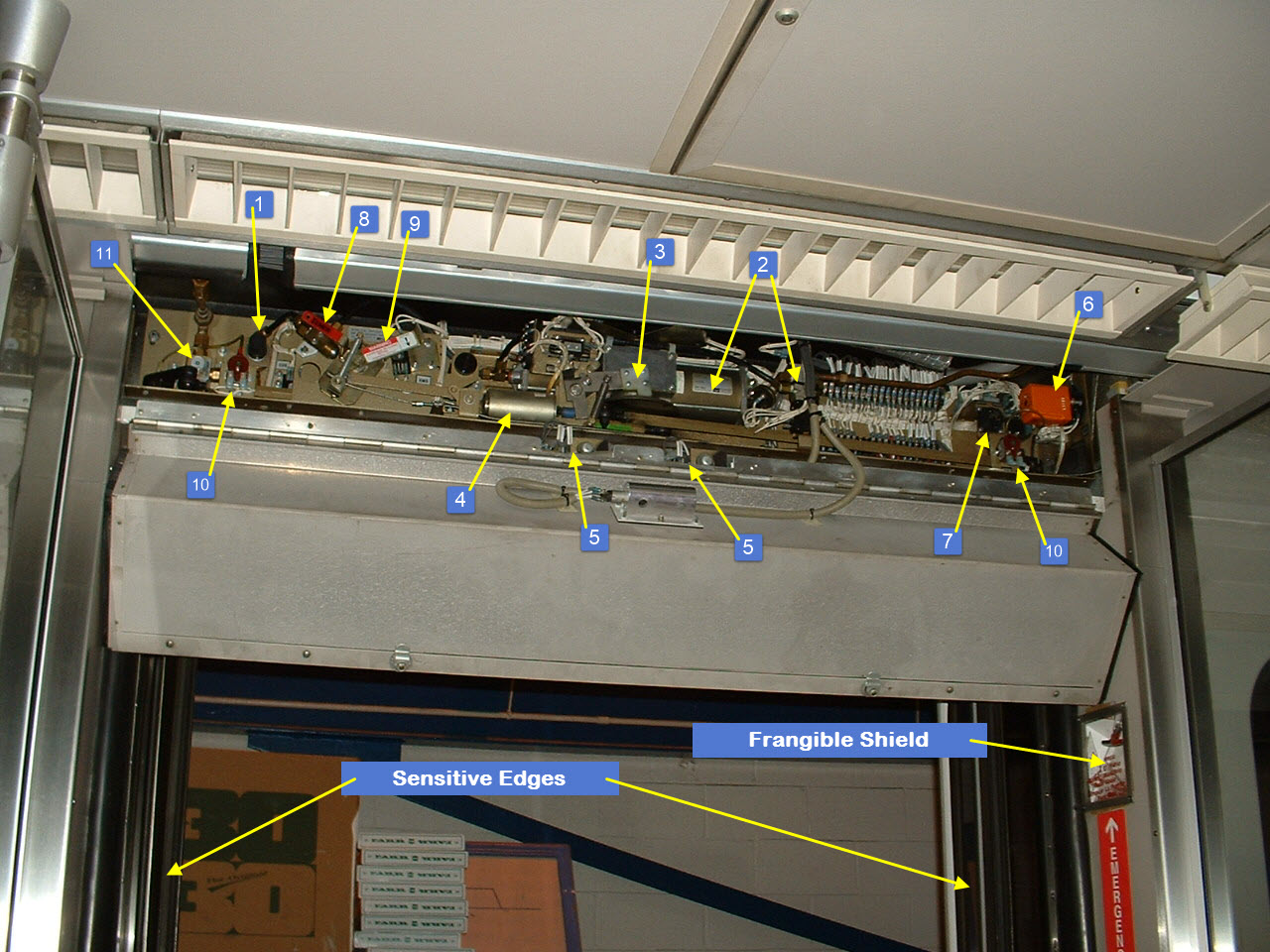 Picture 14-1 The Door Operator.
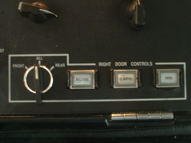 Picture 14-2 Control for the right side doors
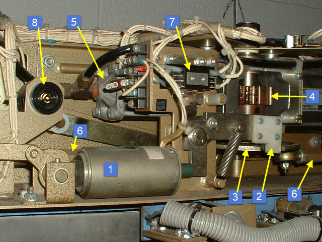 Picture 14-3 Release mechanism
 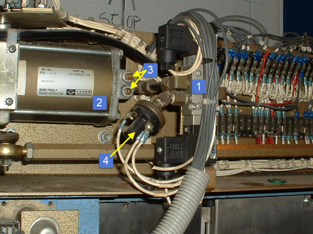 Picture 14-4 Control valve and right engine
 Picture 14-5 Stuff on the right side of the door operator
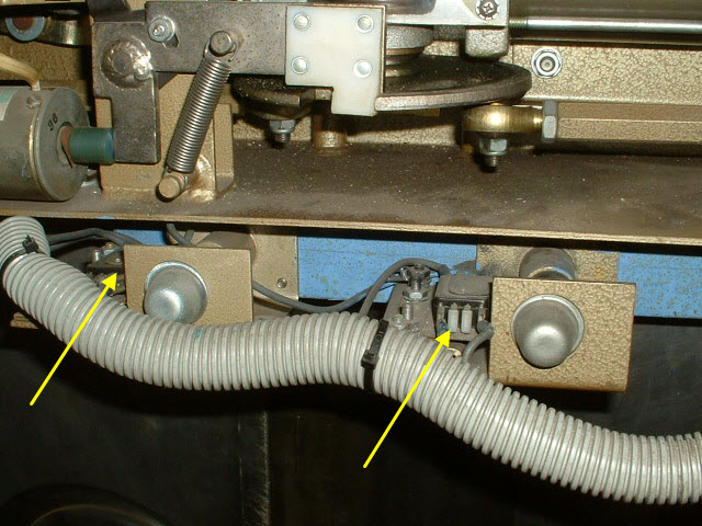 Picture 14-6 Door closed switches
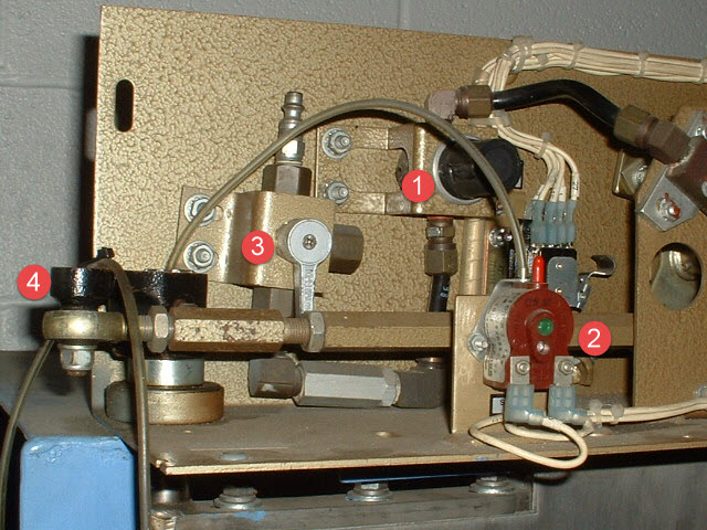 Picture 14-7 Pressure
regulator (1), sensitive edge sensor (2), air shut-off (3), door operating crank
(4)
Picture 14-7 Pressure
regulator (1), sensitive edge sensor (2), air shut-off (3), door operating crank
(4) Picture 14-8 Manual cutout
(1) and emergency valves (2)
Picture 14-8 Manual cutout
(1) and emergency valves (2)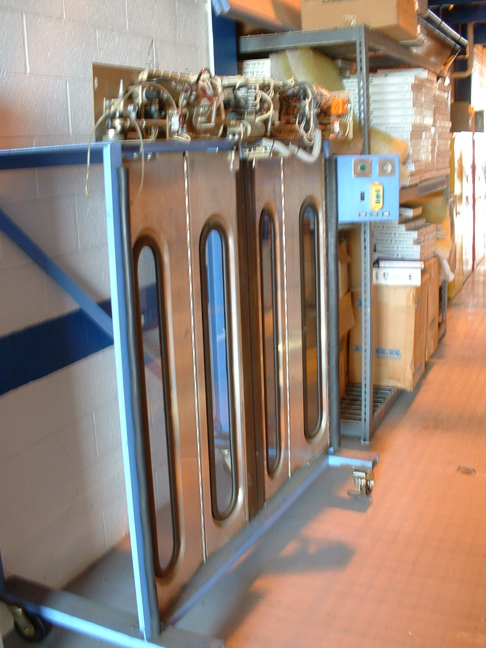 Picture 14-9
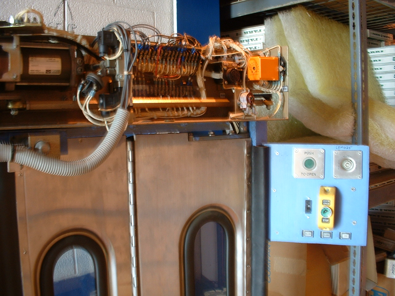 Picture 14-10