◄
PREVIOUS Chapter
 NEXT Chapter ►
CHAP 1 - Introduction
TOP
CHAP 2 - Some Basic Specs
CHAP 3 - Locations of Major Equipment
CHAP 4 - the "TRACS" Computer System
CHAP 5 - the High Voltage, Auxiliary and Propulsion Systems
CHAP 6 - the Low Voltage Systems and Batteries
CHAP 7 - the Air System
CHAP 8 - the Braking System
CHAP 9 - the Suspension System
CHAP 10 - the Trucks
CHAP 11 - the HVAC Units
CHAP 12 - the PA and Intercom System
CHAP 13 - the Pantographs
CHAP 14 - the Doors
CHAP 15 - the Couplers
CHAP 16 - the Lighting System
CHAP 17 - the Destination Signs
CHAP 18 - Winterization
CHAP 19 - Operation
CHAP 20 - Maintenance
CHAP 21 - Floobydust
3.1 The various figures of this section show the locations of the major items. All of the diagrams are oriented with the "A" end to the left, and are top views, looking down.
Figure 3-1 shows the rooftop equipment. The upper drawing is for a single pan car, while the lower drawing depicts the roof for a double pan vehicle, which most are now.
Figure 3-2 gives you the location of the major interior components.
Figure 3-3 shows major undercar components except for the air and brake components.
Figure 3-4 illustrates the brake and air components.
3.2 Coming later:
Figure 3-5 shows the center operators console.
Figure 3-6 shows the left console.
Figure 3-7 shows the right console.
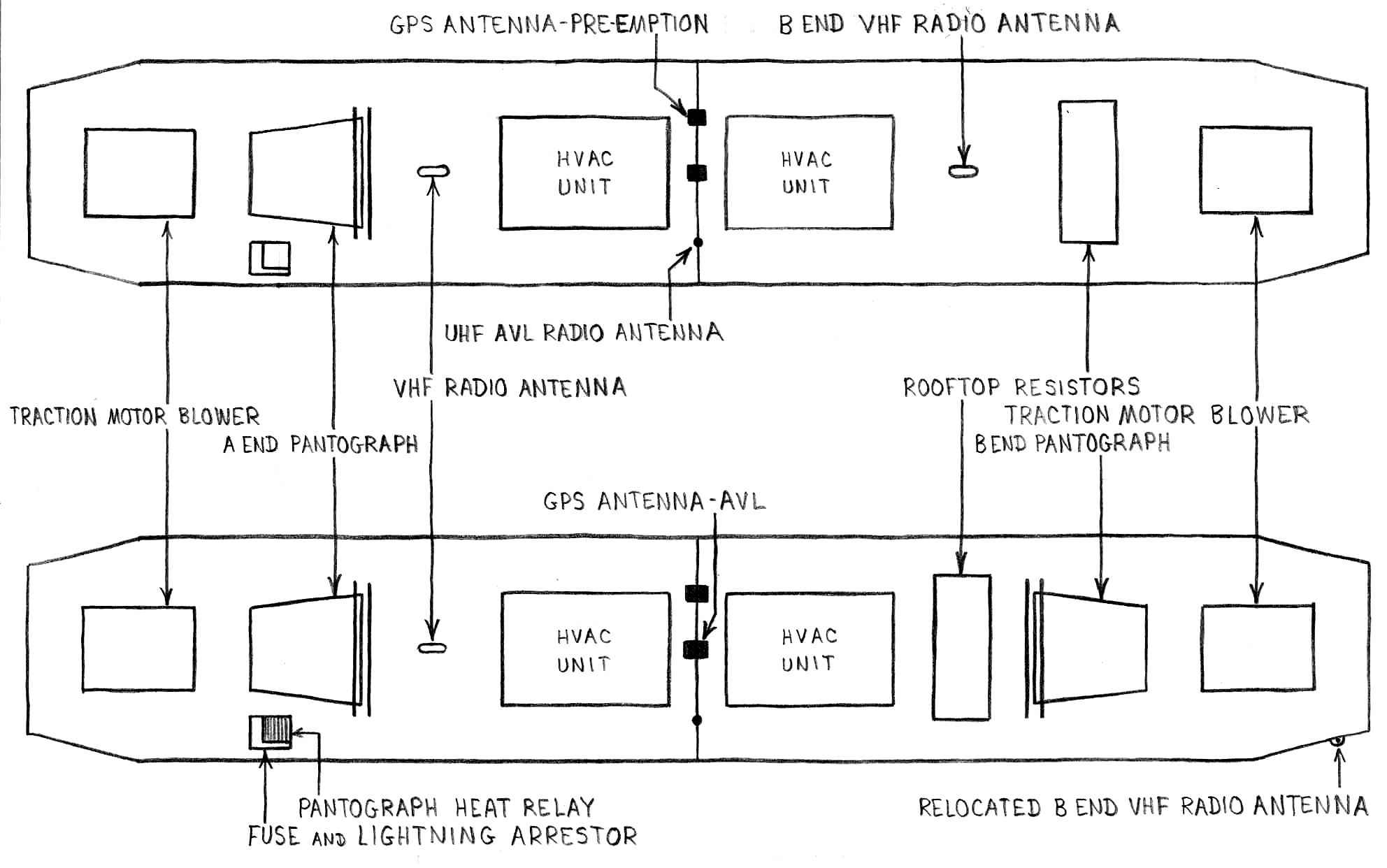
Figure 3-1 - Rooftop Equipment
Around 1996, the MTA started adding a second pantograph to the top of the LRV's
on the B end, to use a ice scrappers during the winter.
In order to do this, the braking resistors and VHF antenna were relocated to make room....
The right side clearance light on the B end was removed to make room for the VHF antenna, now a quarter wave whip.
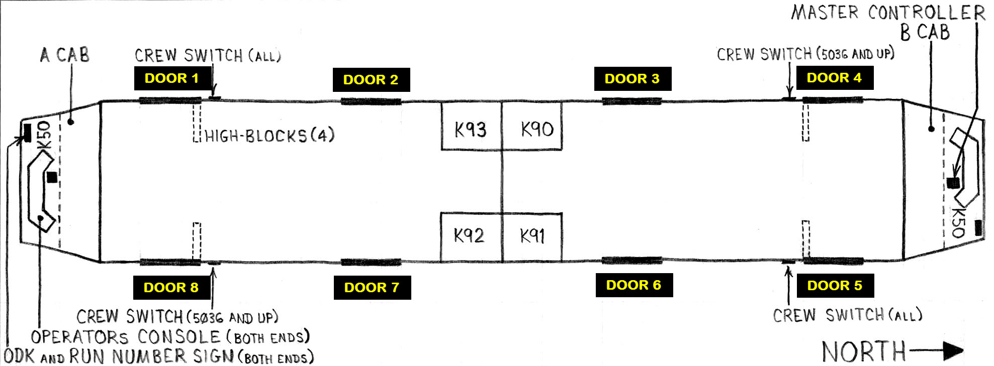
Figure 3-2 - Major Interior Components
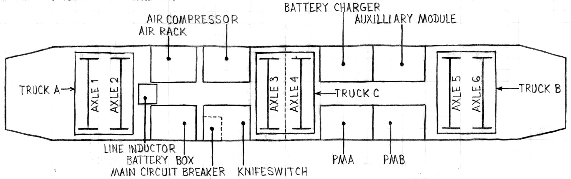
Figure 3-3 - Major Undercar Components
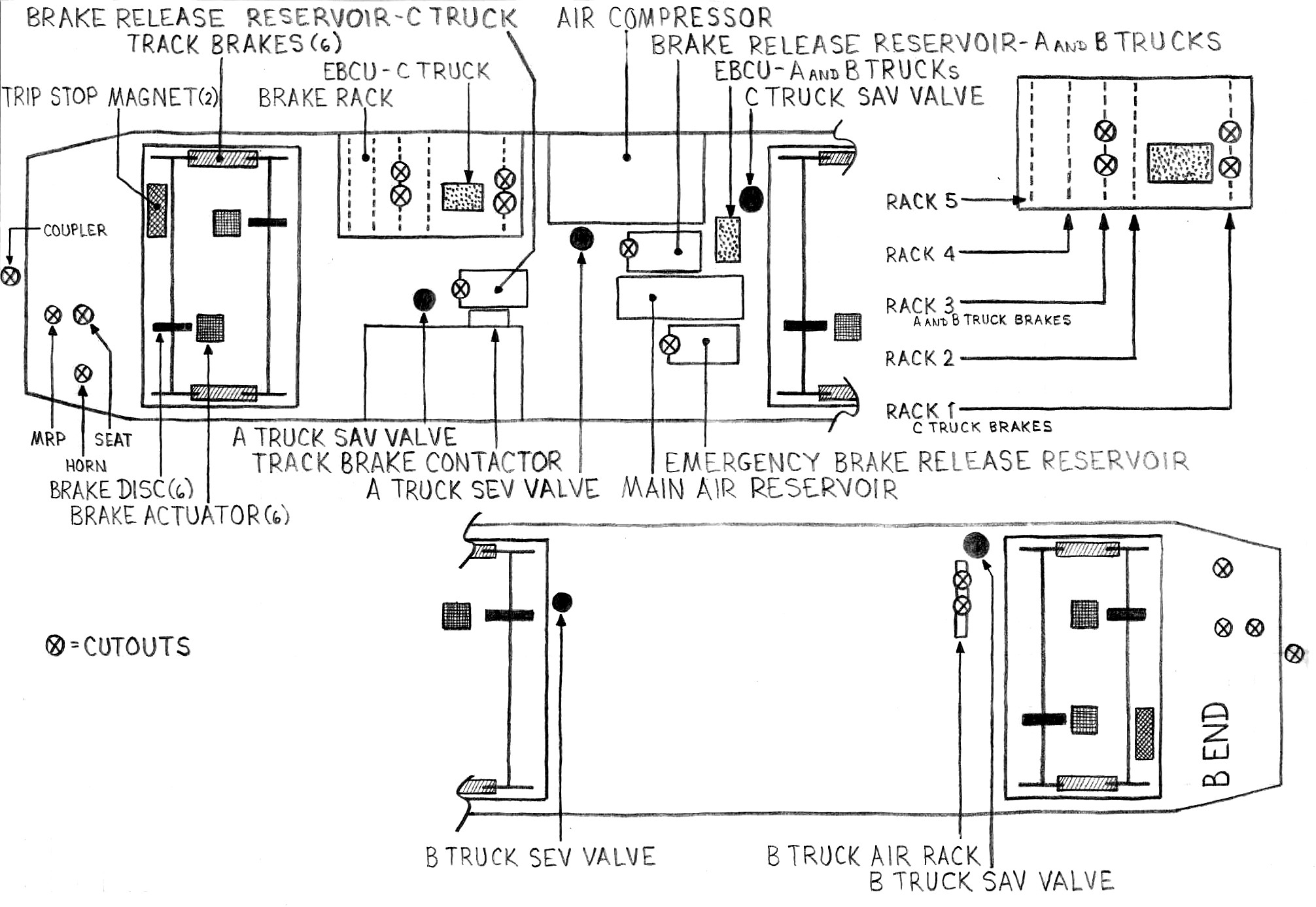
Figure 3-4 - Brake and Air Components
◄
PREVIOUS Chapter
NEXT Chapter ►
New 10/6/2006....
Last Modified
Friday, 07 April 2017