CHAP 1 - Introduction CHAP 2 - Some Basic Specs CHAP 3 - Locations of Major Equipment CHAP 4 - the "TRACS" Computer System CHAP 5 - the High Voltage, Auxiliary and Propulsion Systems CHAP 6 - the Low Voltage Systems and Batteries CHAP 7 - the Air System CHAP 8 - the Braking System CHAP 9 - the Suspension System CHAP 10 - the Trucks CHAP 11 - the HVAC Units CHAP 12 - the PA and Intercom System CHAP 13 - the Pantographs CHAP 14 - the Doors CHAP 15 - the Couplers CHAP 16 - the Lighting System CHAP 17 - the Destination Signs CHAP 18 - Winterization CHAP 19 - Operation CHAP 20 - Maintenance CHAP 21 - Floobydust
7.1 ABB considers the air system as just the air compressor, but for the sake of this discussion, I will also include the storage tanks, some of the air lines and some of the shut off valves.
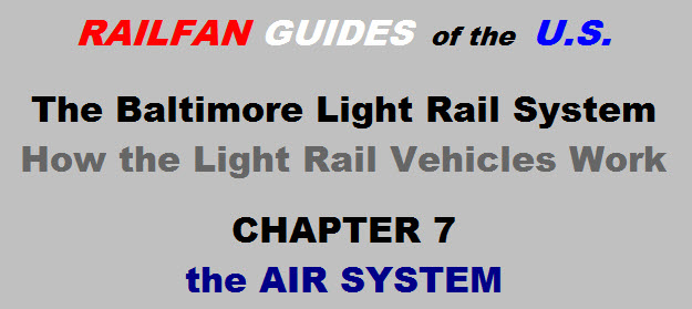
7.2 The air compressor has been pretty reliable, considering how leaky the air system is and often it has to run (especially when the operators sit there and "play" with the master
controller). It is a two-stage, three cylinder unit powered by a 10hp, 220VAC, 1750RPM, three phase motor. The output capacity is rated at 23CFM. There is an oil bath filter on the air intake,
and an air dryer on the output. Between the two stages there is an intercooler, it is located on the "outside" of the air compressor (just under the skirt). Before the dryer, there is an
aftercooler (it's located on the "inside"). Two cylinders make up the first stage, taking the pressure up to around 60PSI. There is a relief valve rated for 75PSI on the output to protect the
cooler. The second stage takes the pressure up to a range of 130-150PSI, which are the setpoints for the compressor switch. The aftercooler is protected by a 200PSI safety valve. The air compressor
(and dryer) is fairly easily removed as a unit, involving only two cables, a ground strap, the air line, and four bolts. By "outside", I refer to the side of the compressor frame that faces you as
you lift up the skirt from trackside. "Inside" refers to what you have access to from underneath the car while it is over a pit.
Picture 7-1 An air compressor in the maintenance shop, dryers facing us.
Picture 7-2 Air compressors on the mezzanine shop floor.
7.3 The compressor is controlled by a motor governor pressure switch. It should be adjusted so the "cut-in" point is between 127-133
PSI and the cutout pressure is between 147-153 PSI. The pressure switch is located on the "outside" of the compressor frame, housed in a square waterproof electrical box about 4"
square.
7.4 The air dryer is a twin tower unit, with desiccant balls used as the primary moisture absorbent. While the compressor is operating, the towers switch off every 60 seconds. When they
switch, you will hear a short blast of air coming out the air dryer, getting rid of the moisture. The timer circuit remembers which tower was in use when the compressor stopped, and will resume the 60 second
cycle where it left off.
7.5 Air from the compressor goes into a 250L storage tank. From there it goes out to the various systems by way of a 5/8" copper line. This line is aptly referred to as the
main reservoir pressure, or MRP. The MRP is also a “trainlined” function, and the round rubber seal on the face of
the coupler connects the MRP line of one car to another, allowing one car to supply another in the event of a compressor failure in one car of a multiple car lash-up.
Picture 7-3 The MRP Valve on the face of the coupler.
7.6 The MRP line directly feeds such things as the brake system, suspension, doors, couplers, horns, and operator seats.
7.7 In each of the operators cab, the white needle of the air pressure gauge is connected directly to the MRP line (thru a shutoff valve under the cab). The other (red) needle indicates the brake line
air pressure, and is discussed in chapter 8 (I had to photshop my image out of the picture :-).
Picture 7-4 The pressure gauge in each cab's operators console.
7.8 Air is used for:
The train brakes.
The horn.
The door operators.
The sanders.
The coupler centering device.
The electrical head extension piston.
The operator’s seat.
7.8
Figure 7-1 is a drawing of the basic air circuit
 NEXT Chapter ►
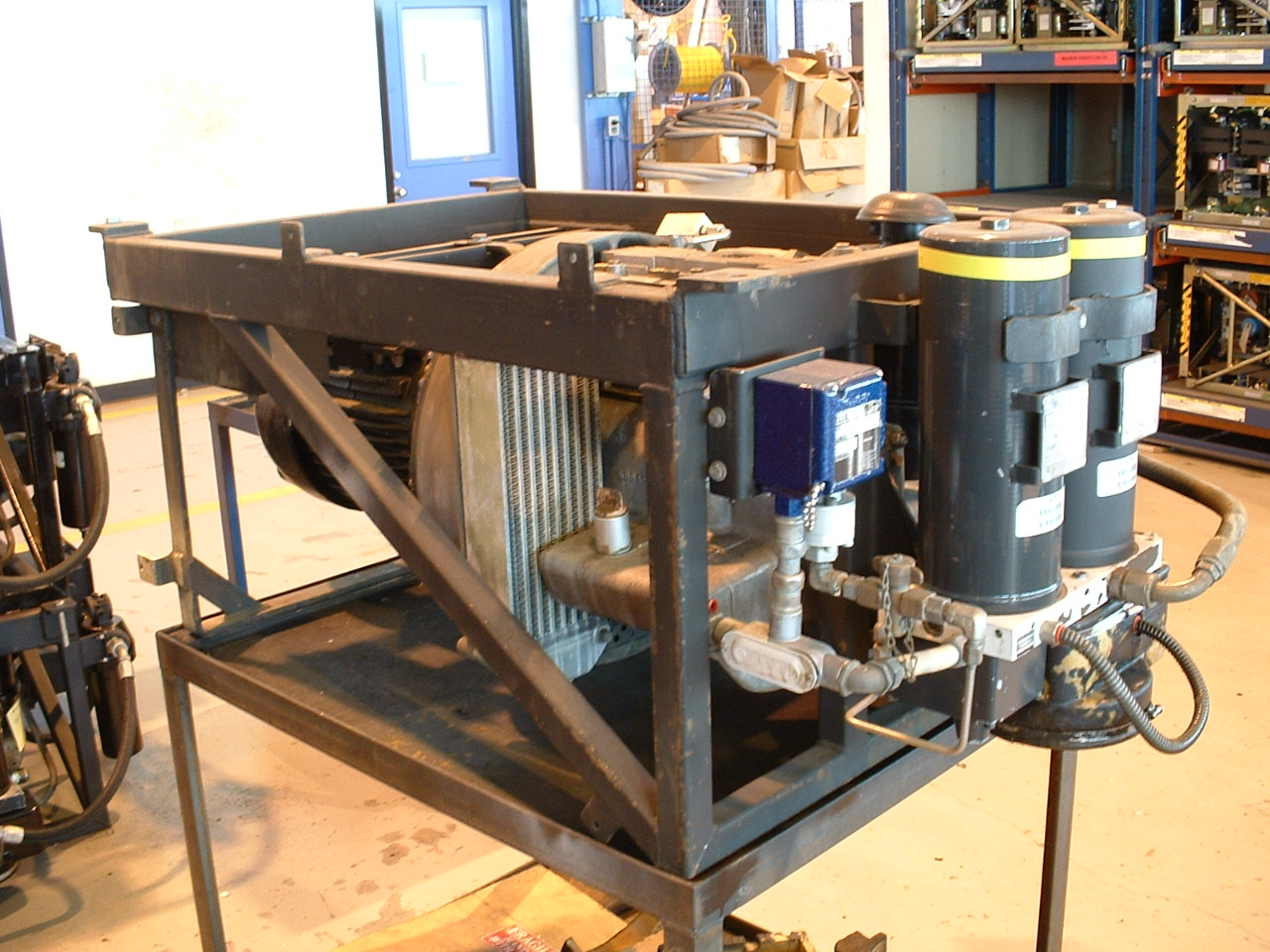 Picture 7-1 An air compressor in the maintenance shop, dryers facing us.
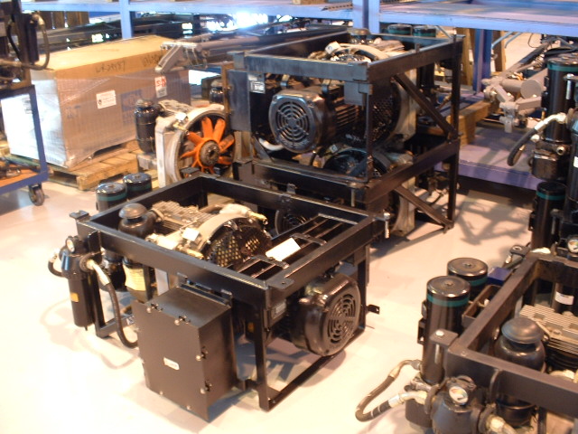 Picture 7-2 Air compressors on the mezzanine shop floor.
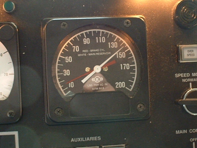 Picture 7-4 The pressure gauge in each cab's operators console.