CHAP 1 - Introduction CHAP 2 - Some Basic Specs CHAP 3 - Locations of Major Equipment CHAP 4 - the "TRACS" Computer System CHAP 5 - the High Voltage, Auxiliary and Propulsion Systems CHAP 6 - the Low Voltage Systems and Batteries CHAP 7 - the Air System CHAP 8 - the Braking System CHAP 9 - the Suspension System CHAP 10 - the Trucks CHAP 11 - the HVAC Units CHAP 12 - the PA and Intercom System CHAP 13 - the Pantographs CHAP 14 - the Doors CHAP 15 - the Couplers CHAP 16 - the Lighting System CHAP 17 - the Destination Signs CHAP 18 - Winterization CHAP 19 - Operation CHAP 20 - Maintenance CHAP 21 - Floobydust
10.1 Each LRV has three trucks. The center truck, under the articulated section, is unpowered. The other two, one under the "A" section and one under the "B"
section, are powered. The non-powered truck has a slightly different frame, since it does not contain any motors. A fully built up center truck weighs 9526 pounds (4330 kilos), and a powered truck
weighs 13882 pounds (6310 kilos). The trucks were manufactured by AAI in Cockeysville MD, located north of Baltimore. They are fabricated of welded sheet steel instead of being cast. Each truck
assembly consists of: two axles, two track brakes, the suspension system, two friction/disc brake assemblies; and for the powered trucks: two motors and transmissions, two sanding tubes, and a trip stop unit.
Picture 10-1 A couple of power trucks sitting on the shop floor
10.2AXLES: All three trucks are two-axle types. The axles rotate in roller bearings, which so far have not required replacing. The end of a
powered axle is shown in picture 10-2. The bulge is for the drive gear, which when fully assembled, will be inside the transmission case. Pictures 10-3 and 10-4 show a bearing mounted on the axle.
Picture 10-2 End of an axle before the bearing and wheel are installed.
Picture 10-3 Roller bearing mounted on the axle
Picture 10-4 Close-up of the roller bearing
10.2.1 The roller bearings mount in a journal box (picture 10-5), which in turn, rests in between two chevrons (pictures 10-2 and 10-3). The chevrons are made up of alternate layers of
rubber and "V" shaped steel plates. As mentioned in the last chapter, the chevrons are the main suspension for the LRVs. If you notice in the picture below, there is a bar underneath the
journal box. The purpose of this bar is to prevent the axle from lowering too far and dropping out of place when the truck is lifted for maintenance.
Picture 10-5 The Chevrons and the Journal Box
Picture 10-6 Close up of a Chevron
10.2.2 All six axles have a slight machined bulge, where the brake discs are bolted on. Picture 10-7 shows the bulge with a brake mounting collar installed.
Picture 10-7 "Brake bulge"
10.2.3 The four motorized axles also have a pressed on gear, which, when assembled, sits inside the transmission case.
10.3 The wheels are 28” when new, and are made of two pieces separated by rubber inserts. The wheels are pressed onto the axle, and do not normally need to come off.
The tire is the "outside" part of the wheel, and it is pressed on to the “inner” part of the wheel. The two are isolated by
rubber inserts. The purpose of these inserts is to provide some degree of wheel noise quieting. Originally, the electrical grounds were provided by a copper core in every third rubber
insert. However, after a while, the constant compression and decompression as the wheel rotated, made the electrical contact less than reliable - so four shunts were installed on each grounded wheel.
Picture 10-8 A stack of new wheels
10.4 A thickness of 1" can be worn and/or taken off before the tire is condemned and needs to be replaced. There is a wear indicator (a groove) on the tire, showing the wear
limit. Wheels are turned down usually for two reasons: 1) They have developed larger than usual flat spots, or 2) The profile, or contour of the wheel is out of
specification. The Hegenscheidt machine is used to turn down the wheels, and is sort of a specialized lathe. In order to minimize wheel wear, the profile of the wheels and that of the rails should
match. Los Angeles had a severe wheel wear problem on their newly opened heavy rail system before it was discovered that the rails had a completely different profile than the wheels. Inside the computer compartment is a selector switch to compensate for the changing wheel size, but I don't know if anyone has ever used this switch as the
wheels have gotten smaller. The switch is graduated in 1/4" steps, from 28" down to 26".
10.5 Up in Hunt Valley, there are five tight turns. The MTA engineers shot down an MOW request for putting in wayside type rail lubricators, citing that they
would dirty the pretty white concrete ties. Who cares as long as it saves wheel wear?
10.6 So...... One effort that was taken to reduce wheel wear was the installation of flange lubricators. I am skeptical on their effectiveness, because the wheels still squeal when going around
(sometimes) even a mild curve. However, even the slightest bit of rain or dew on the rails, and the wheels no longer squeal, so how effective can the flange lubricators be? It's
too bad it freezes around here in the winter, for Dallas came up with a great idea, where they have holes in the rails where they constantly have a trickle of water flowing.... Sweet and simple! :-)
10.7 Replacing the tire used to involve cutting the tire into several pieces by hand with a gas powered cutter. In 1997, we purchased a (huge) machine for pressing the tires on and
off.
Picture 10-9 Tire press
10.8 Grounding of the axles is accomplished by ground cables going to a ground brush assembly. The ground brush assembly contains three spring-loaded carbon brushes. They get
checked on the annual inspections. A 5/8" socket is needed to remove the assembly, and a 9/16" socket is needed to take off the ground cables. Axle hubs 1E, 1W, 2E, 5W, 6E,and 6W have
these assemblies on them. Axle hubs 1W and 6E have mileage "hub-dometers" on them.
Picture 10-10 Grounding an axle
Picture 10-11 A hub-dometer
10.9 Each powered truck also contains two motors, one driving each axle through a gearbox, or transmission as they call it. The motors are sealed, have no brushes in them (that
would necessitate replacement), and have permanently lubricated bearings. After the initial delivery of the first batch of cars in 1989/90, the MTA experienced a few early failures with the motors.
After a short investigation, it was found out that some of the motors had been shipped with low speed bearings. This problem was corrected before the LRV’s went into service in 1991. The following set
of pictures illustrate the motors and the transmission. One of the many speed sensors that transits speed info on the motor can be seen in the upper portion of picture 10-15.
Picture 10-16 Close-up of the input shaft to the transmission
Picture 10-17 Close-up of the transmission input and speed sensor
Picture 10-18 Gearbox input close-up
Picture 10-19 Gearbox input
10.10 Removal and installation of the trucks is not as bad a job as it may seem. The job is usually performed on shop track 2 south (2S). There, we have a set of “built-in”
car jacks which are capable of lifting up the entire car. When the car is placed over the jacks and blocked into place, one button on the jack control will raise and lower the entire car. Once the
car is elevated to working height, and the car jacks are locked into place, work on the trucks can commence. After the wires and brake lines have been disconnected, there is a separate jack for each
truck, so that they can be raised and lowered independently of the car itself. Once down, the trucks have the disc brakes cranked off, and can then be rolled into the truck shop, via a small turntable
between the north and south pits. In the “truck shop” area, there is a ten ton overhead crane to assist with the repair process. Located adjacent to the repair area, is a cleaning room, where the
trucks get pressure washed and steam cleaned before working on them. The HVAC units are also cleaned in this room as part of their annual check-up.
10.11 In 2000, when the trucks were given a 10 year overhaul, they affixed a sticker to the trucks as seen below in picture 10-20. Don't know if they did the same thing in 2010
for the 20 year overhaul.
 NEXT Chapter ►
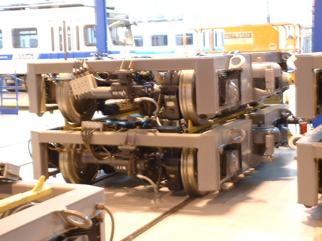 Picture 10-1 A couple of power trucks sitting on the shop floor
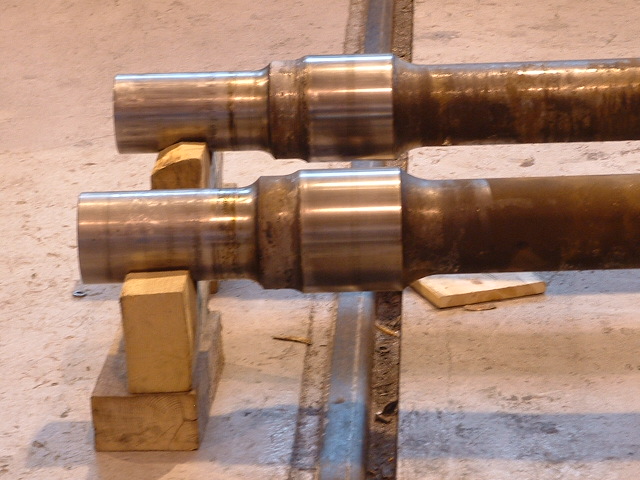 Picture 10-2 End of an axle before the bearing and wheel are installed.
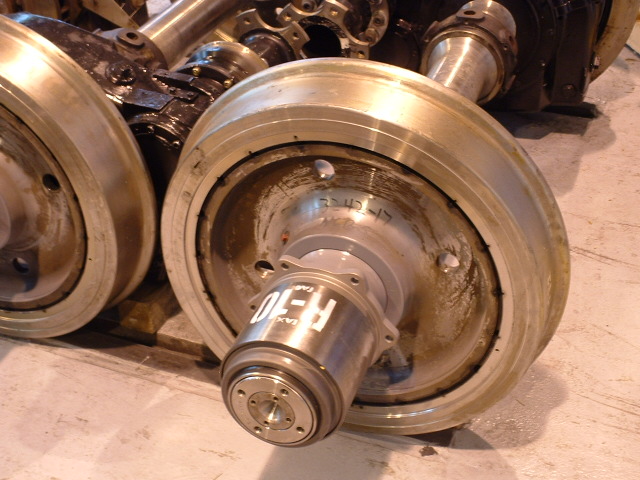 Picture 10-3 Roller bearing mounted on the axle
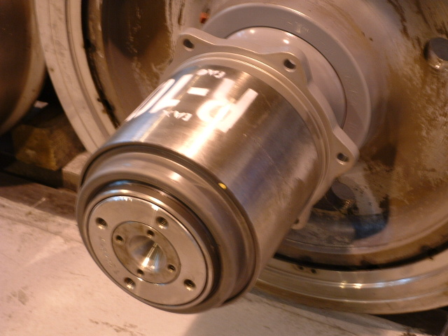 Picture 10-4 Close-up of the roller bearing
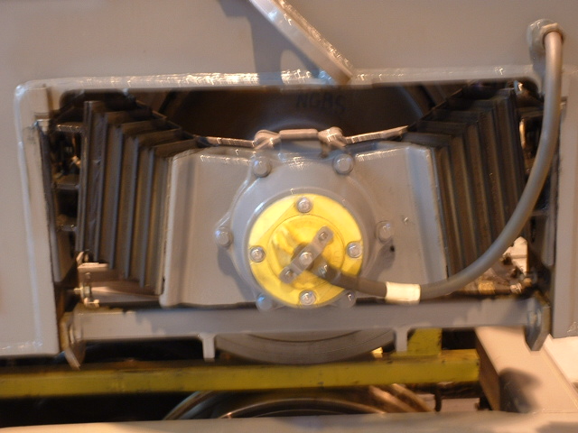 Picture 10-5 The Chevrons and the Journal Box
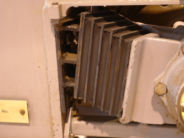 Picture 10-6 Close up of a Chevron
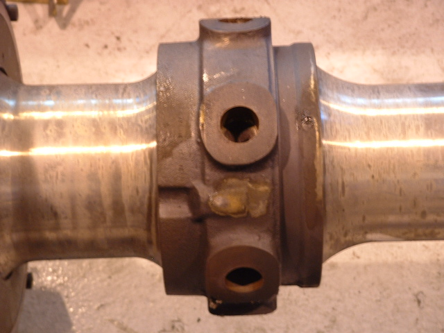 Picture 10-7 "Brake bulge"
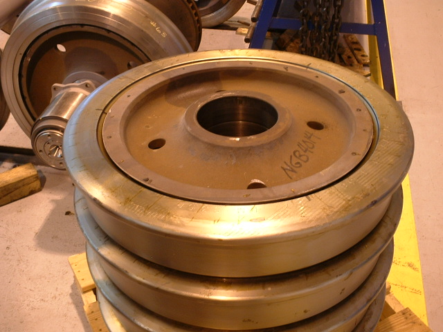 Picture 10-8 A stack of new wheels
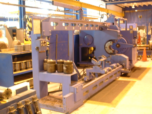 Picture 10-9 Tire press
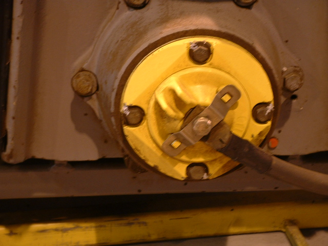 Picture 10-10 Grounding an axle
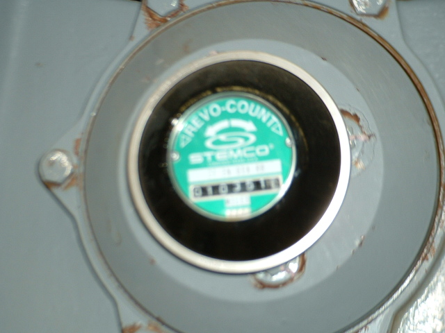 Picture 10-11 A hub-dometer
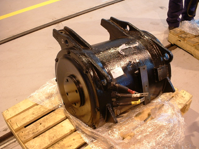 Picture 10-12 A motor waiting for installation
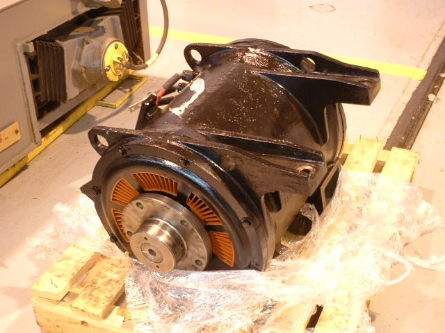 Picture 10-13 The other end of a motor
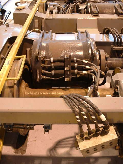 Picture 10-14 Motor installed in the truck
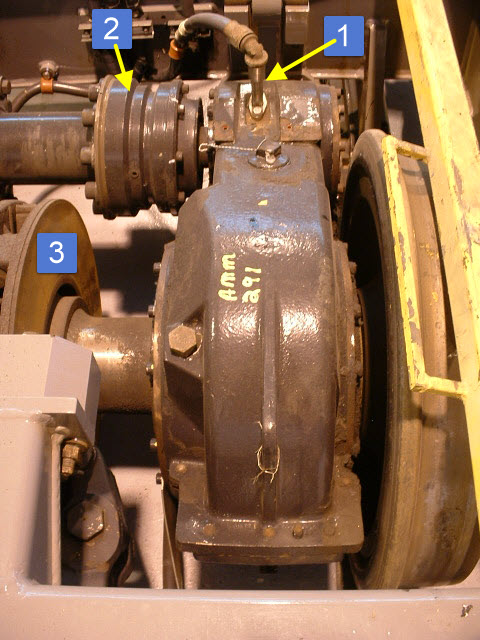 Picture 10-15 The transmission case, or gearbox
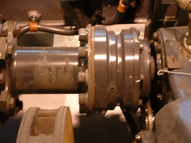 Picture 10-16 Close-up of the input shaft to the transmission
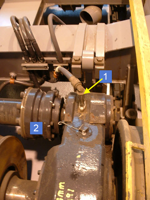 Picture 10-17 Close-up of the transmission input and speed sensor
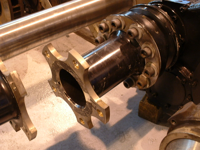 Picture 10-18 Gearbox input close-up
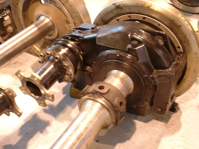 Picture 10-19 Gearbox input
  Picture 10-20 A 10 year overhaul sticker