CHAP 1 - Introduction CHAP 2 - Some Basic Specs CHAP 3 - Locations of Major Equipment CHAP 4 - the "TRACS" Computer System CHAP 5 - the High Voltage, Auxiliary and Propulsion Systems CHAP 6 - the Low Voltage Systems and Batteries CHAP 7 - the Air System CHAP 8 - the Braking System CHAP 9 - the Suspension System CHAP 10 - the Trucks CHAP 11 - the HVAC Units CHAP 12 - the PA and Intercom System CHAP 13 - the Pantographs CHAP 14 - the Doors CHAP 15 - the Couplers CHAP 16 - the Lighting System CHAP 17 - the Destination Signs CHAP 18 - Winterization CHAP 19 - Operation CHAP 20 - Maintenance CHAP 21 - Floobydust4.1 First of all, let's set the record straight: TRACS, according to ADtranz, doesn't stand for anything. The computer is of a proprietary design, so there is nothing out there
made by anyone else that will interchange with it. The computer is based on a Motorola 68000 series micro-processor. The computer is the heart of the LRV, because without it, little else functions.
Exceptions are: 1) The battery charger, 2) The door circuits, 3) Some of the lights, 4) Most of the operator console controls will work, 5) The emergency loop (providing the correct cutouts have been thrown), and
6) The radio. The computer is located in the K90 locker, right side of the articulated section as you look towards the "A" cab.
4.2 A quick note about the software. In addition to the design of the computer, the software is also proprietary. And, because of legal ramifications, the MTA does not make
any modifications to the operating software. Besides, ADtranz won't give us either the software listing or de-compiled code, probably because they want to get the $10,000 or so it costs the MTA to make a
single change in the software.
4.3 Several power supplies running off the 39 volts, power the computer. This enables the computer to continue operating in the event of a battery charger failure and/or loss of high-
voltage. Unfortunately, the 24 volts from one of the supplies is also used to power things like the speed sensors, and in the past when a cable to one of them has gotten damaged, it usually takes out the
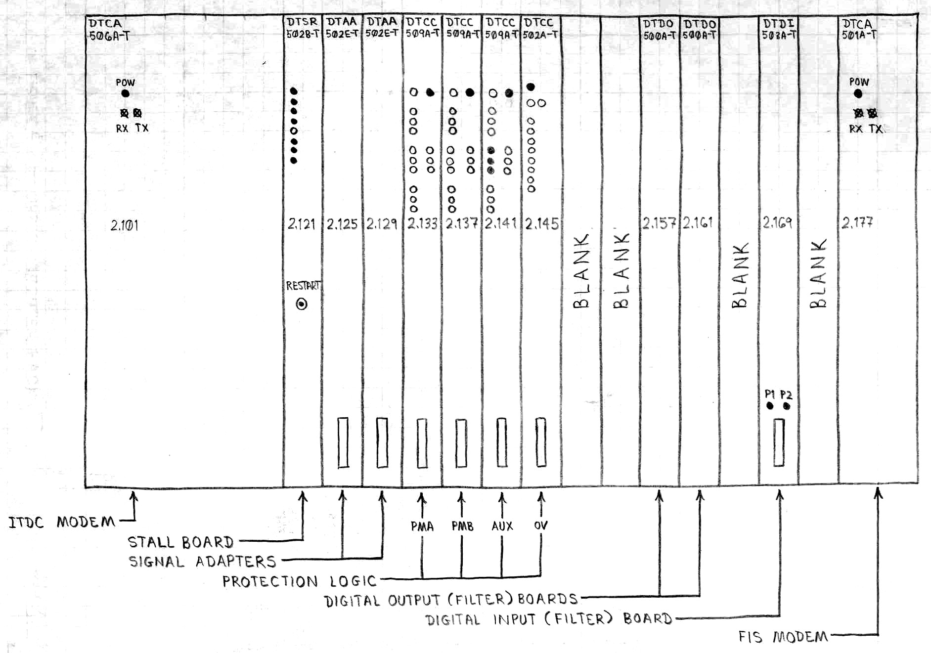
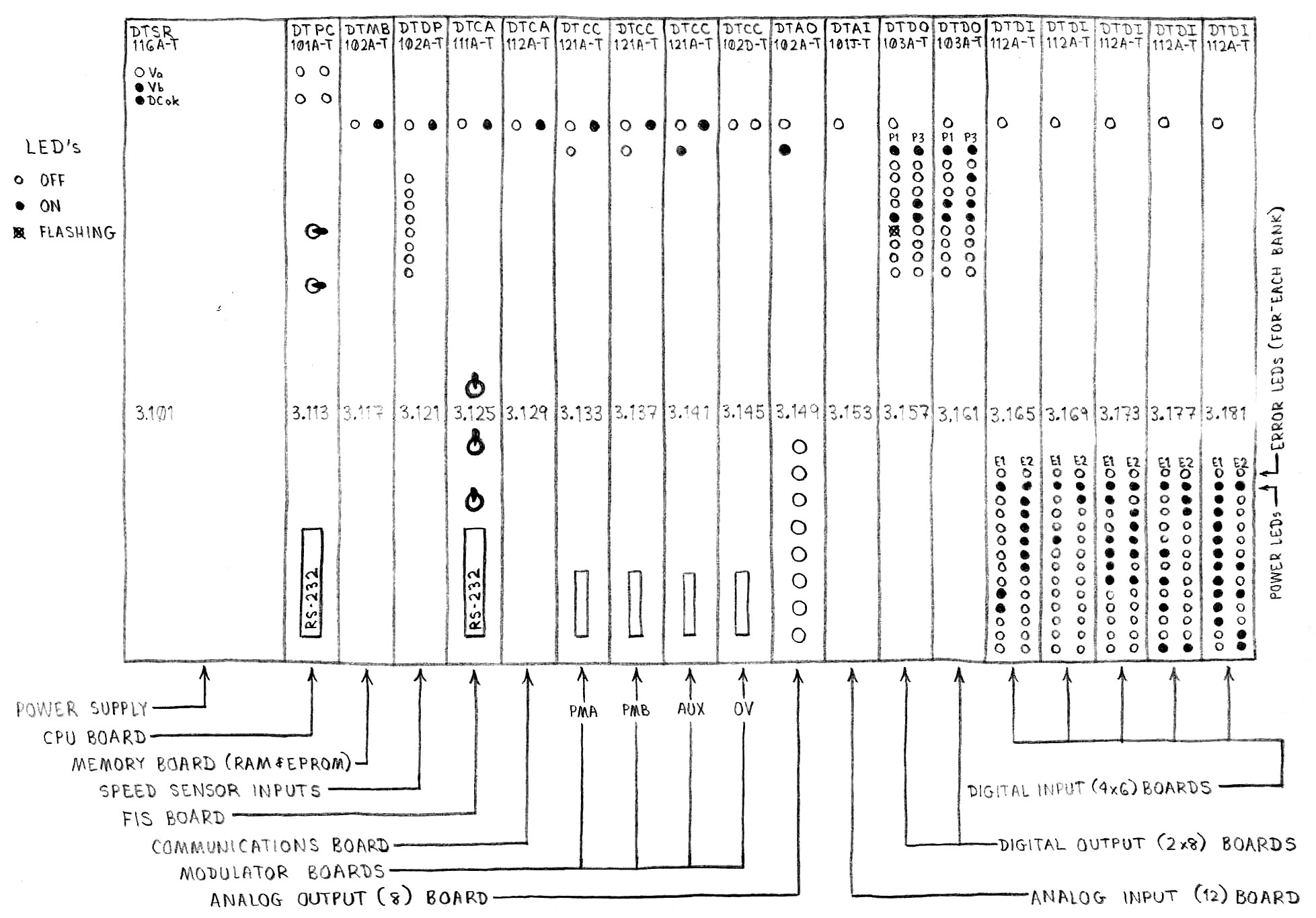
power supply and kills the computer. One of the power supplies is located to the right of the ITDC modem. The other is located in the lower rack, all the way to the left.
4.4 Most of the inputs to and outputs from the computer are digital. There are two DTDO digital output boards on the upper rack. There are five DTDI digital
input boards on the lower rack. This gives you 32 output and 80 input channels.
Figure 4-1 Upper TRACS Computer Rack
4.5 The speed sensors go into additional digital inputs on the DTDP board at location 3.121. There is set of six LEDs, which act as status lights when the speed sensors are providing a
viable input.
Figure 4-2 Lower TRACS Computer Rack
4.6 Digital outputs from the computer directly drive the GDU (Gate Drive Units) boards in the propulsion modules and the auxiliary converter. They originate from the 3.157 board.
4.7 Analog inputs to the computer are the: 1) Two master controllers, 2) Hi-voltage LEM (transducer), 3) (Hi-V) overcurrent LEM, 4) (Hi-V) differential current LEM, and 5) Six temperature
sensors in the motors (thermistors). And no, LEM does not stand for "Lunar Excursion Module", it is the manufacturer of the transducers. Analog outputs from the computer go to the: 1)
Speedometers, 2) Brake EBCU's, and 3) Five programmable outputs for the chart recorder.
4.8 A laptop computer can be connected to the TRACS computer through an RS-232 port on the front of the 3.113 (DTPC) module. Any standard terminal program can be used for access.
Setup for connection is established at 9600,8,1,0. Once in, you will get a ">" on screen, sort of like the DOS prompt. From here, you can access almost any software parameter the computer
deals with, let me give you two examples: 1) You can set up a "trigger" to record certain events for the purpose of troubleshooting, and then download them at a later time. 2) You can
program the "programmable" outputs, and record the signals you want on paper or view them on an oscilloscope (for a test like the brake rate test talked about at the end of section 8). You can
change variables while the computer is running, computed ones as well as those stored in ROM, although the computer loses those values when shut down. You could if you wanted, run the LRV completely from the
laptop, fooling the computer into thinking the master controller is at full power and the doors were closed, but it's not very advisable (or smart).
4.9 The computer talks to the other computers in a multi-car consist by way of a modem and the ITDC trainline. This is sort of an 80 volt version of the IEE-422 signal. ITDC
stands for: Internal Train Data Communications. The modem is on the upper rack, left module, and takes up five board spaces.
4.10 The computer software will allow a maximum of six cars to be MU'ed together and still operate as a train.
4.11 The time that is displayed on the FIS can only be changed if a switch on the 3.125 module (DTCA) is in the ENABLE position (down).
4.12 In the original software version of the first 36 cars, we found a problem with the door open recognition routine. If two cars are coupled together (like they do at North Avenue around
3pm), the southbound train has its additional cars added to the rear. If the operator does not key down, he could drive off with the doors open. This probably has more to do with the fact that the
lead computer doesn't know there are additional cars in the consist until the cab is keyed-up (the computer only checks for other cars during the key-up process).
 NEXT Chapter ►