This signal was replaced by color lights in late 2012.
RAILROAD SIGNALS of the U.S.
This signal was replaced by color lights in late 2012.
B&O COLOR
POSITION LIGHT (CPL) SIGNALS
For Starters
Signal
Variations
Signal Pictures
Other Pictures
For CPL and PL signals in Perryville MD, click
here.
For CPL and PL signals from Aberdeen MD north, click here.
RAILFAN GUIDES HOME
RAILROAD SIGNALS HOME
FOR STARTERS
Background
The
Mechanics of the CPL Signal
The
CPL Lamp Assembly
CPL
Primer
the Aspects
Catalog Drawings
Michael Watnoski’s Primer on CPL’s
CPL, or
Color Position Light signals were exclusive
to the Baltimore and Ohio Railroad, and its affiliates. You could find
them anywhere the B&O went. However, now that all of the former
B&O lines are part of CSX, they have been accelerating their efforts to
replace the CPL's with modern 3 color light signals everywhere (yuk).
As with the Pennsy Position Light signals, the B&O Color Position Light signals were an attempt by the designer to simulate, or mimic the position capability of an upper quadrant semaphore signal. But, in contrast to the Pennsy signals, the B&O decided to use color in addition to position for their aspects. This provided a margin of safety in the event one of the two lamps was out.
Other railroads using CPL's are the Staten
Island Rapid Transit (SIRT, now part of the MTA), the former B&O Chicago
Terminal, and the former Chicago and Alton. Dwarf CPL's were also chosen
to be used in and out of Union Station in Washington DC, although they appear
on signal bridges above the tracks.
The first installation of CPL’s on the B&O was between Deshler and Hamlet OH. In December of 1924, the B&O announced that it had ordered 77 sets of CPL’s for the Staten Island Rapid Transit, and they are still in use today despite an announcement several years ago that they were going to replace them.
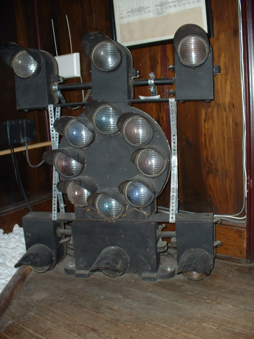
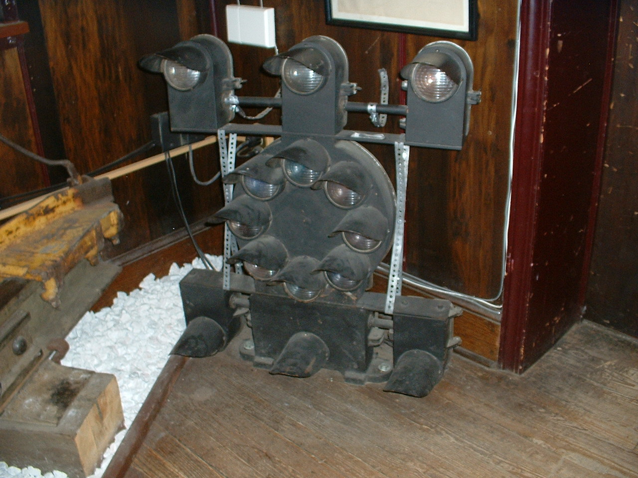
CPL dwarf signals also enjoy being the
only dwarfs which, if so outfitted, can display ALL of the aspects of a high
signal. The only one I ever saw so configured was at the B&O Railroad
Museum in Baltimore. However, I don't know if the signal before it came
to the museum was originally in this form, or if it was put together just for
display. Since the snow cave-in of 2003, the signal has not been on
display because the museum has decided not to use the outside wall for
displaying much of anything.
A fellow by the name of Frank Patenall designed the signals for the B&O around 1925. Patenall came to America in 1885, and worked for US&S before coming to the B&O in 1891. Some sources state that he developed the CPL signal concurrent with the development of the Pennsy’s PL signal, while others say he watched the development of the PL, and then “improved” on it by incorporating color to make it a “safer” signal. BTW, Pennsy installed its first Tombstone PL signals in 1915, so the latter statement may be true. Patenall was also the developer of approach lighting according to Brian Solomon in his book, "Railroad Signaling".
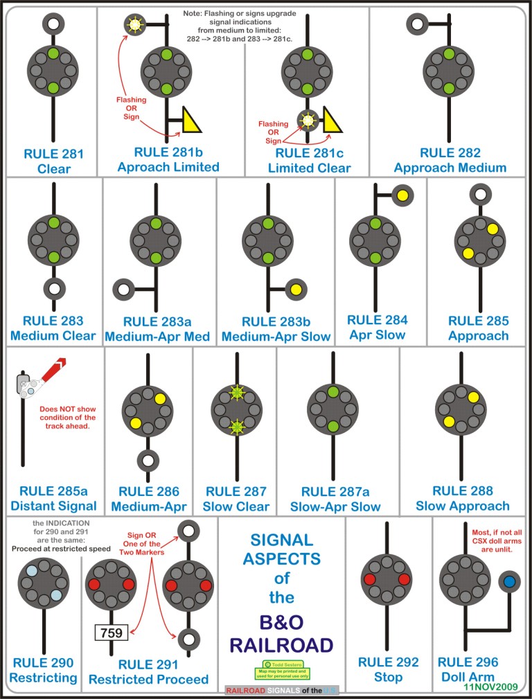
The signal was originally designed to display 14 aspects, but the current CSX rulebook contains 17 of them (it's interesting to note that 10 of them are green variations). Although the signal is capable of displaying 29 aspects (including flashing indications), many would be impractical, such as a slow speed stop, or modifications to the restricting aspect, they just don't make any sense. This is one reason why flashing is used to modify and upgrade a signals indication.
At first, the CPL signal may seem
confusing, but after reading the principles behind it, it’s fairly straightforward
in its interpretation…. There is a system!
The signals were originally manufactured by Hall, but later GRS and US&S made the signals, with the majority of them being made by US&S. The most popular designation for the dwarf CPL is US&S type VA. The full size signal is type “G”, which is why it’s confusing to refer to color light signals as type “G”. Type "G" color light signals are ones with the three aspects in a triangular placement, usually with a round background.
 A
GRS type "G" color light signal for comparison purposes, nicknamed
"trilights"
A
GRS type "G" color light signal for comparison purposes, nicknamed
"trilights"
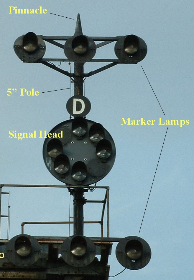
The Mechanics of the CPL Signal
The main CPL signal "head"
consists of a number of individual lamp assemblies mounted to a circular
background 3’-4" in diameter. There could be anywhere from one to as
many as four aspects displayed on the main part of the signal. The pictures below
illustrate some of the
possibilities.
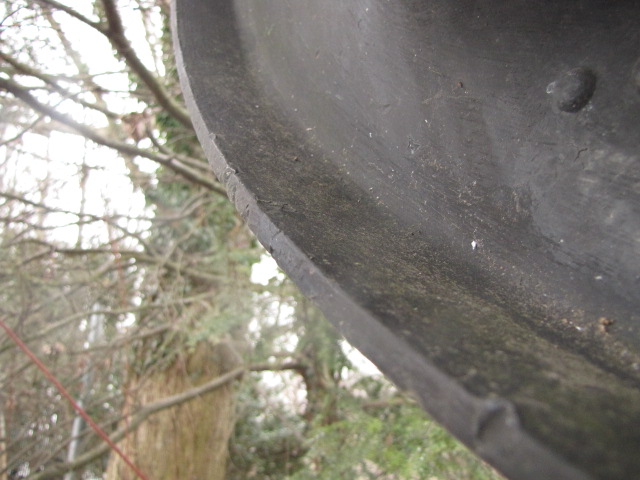
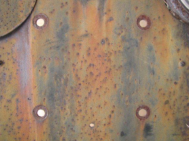
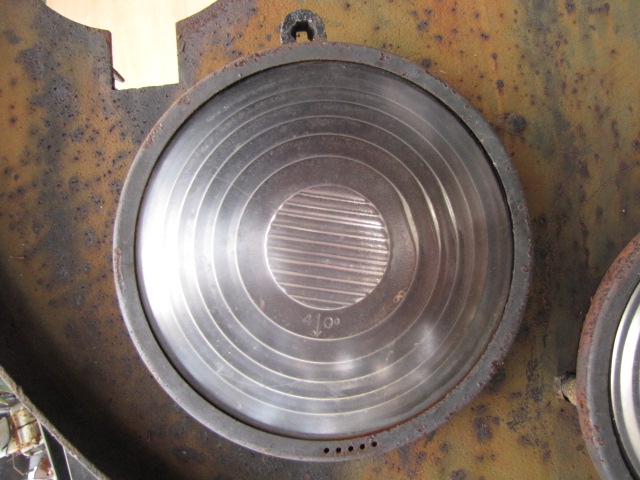
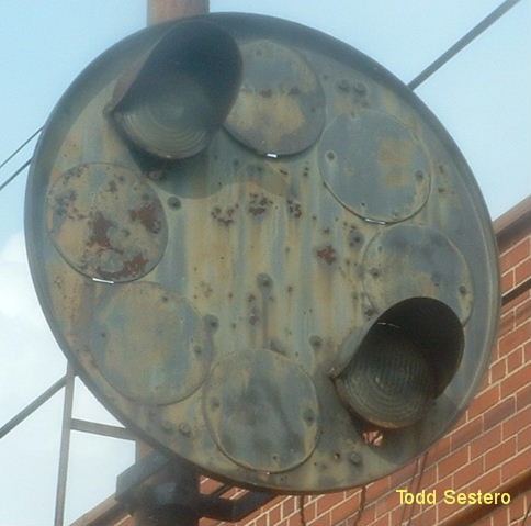
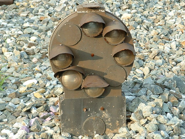
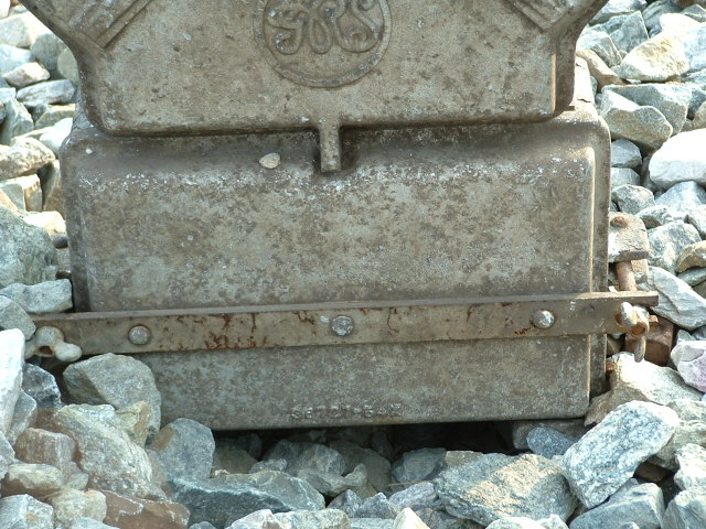
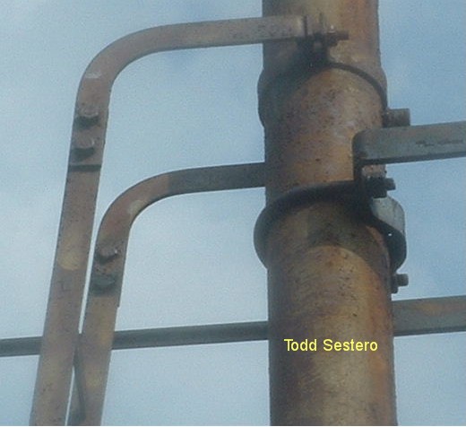
The background is mounted to the mast with two heavy duty steel straps and U-bolts. The background itself is stamped from a piece of 1/4” thick steel, and has a 1 3/4” lip all the way around to strengthen the assembly, since the lamps mount to the background. Newer versions are stamped from aluminum, not sure when the changeover took place. The background has eight 7-5/16” holes stamped in it to allow mounting of the lamp assemblies, three 3/8” holes for each lamp assembly for mounting, and a 11/16" diameter hole above the lamp for sighting/aiming. There are eight (8) 7/16" holes for mounting to the brackets with 3/8" bolts. The two photos below show the lip and the lamp mounting hole.
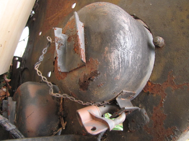
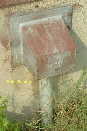
Mounted to the backside of the background
is a junction box, where the cables from the relay cabinet terminate, and
individual wires go out to the lamp assemblies. On some older
installations, a separate transformer was used for each lamp pair, and they
were mounted in the junction box. The
transformers were used to step down the 120VAC to 10-12 volts. Because the 120VAC is mixed in with the low
voltage, they eventually decided to remove them from the junction box
altogether (probably for safety reasons), but also because it was more
expensive to provide a separate transformer for each indication (pure
speculation, though).
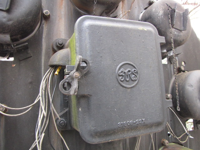
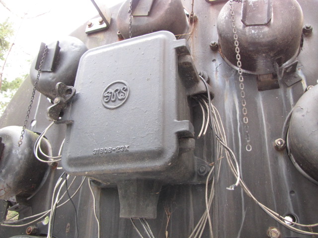
A GRS junction box, and the mounting holes for it viewed from
the front.
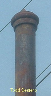
All of this stuff is mounted to a 5" outside diameter mast, up to 20 feet high. If the signal needs to be mounted higher, a 6" pole is used.
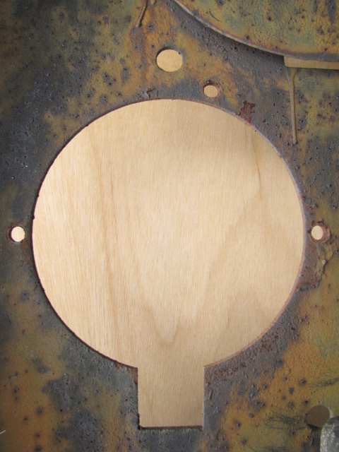
Unused positions are blanked by a 10-1/2" diameter plate, 1/16" thick and held into place by two or three screws, something on the order of #10's.
Most CPL signals also had what are known
as marker lamps located above and/or
below the main signal head. Very few CPL signals consisted just of a main
signal head, most had at least one marker lamp. If it was a high signal,
the sole white marker lamp was usually directly above, so the signal could
display a clear
aspect (rule 281), upgrading the
signal from a slow speed signal….. Without the marker lamp, the green
indication was slow-approach slow
A fully populated CPL would contain
fourteen (14) lamp assemblies, two lamps for each aspect on the main head:
green, yellow, red, and lunar; two (2) yellow markers to the right; and four (4) white
markers to the left and center. Very, very few CPL's have a full
compliment of 14 lamps. The only one around
used to be in Deshler OH, but was replaced with a color light signal around
2006. Baltimore recently (~2008) added a full CPL to the list, and we also
have an almost full signal a little further south, with only the restricting
aspect missing.
According to B&O drawings, the
majority of CPL signals placed on a single mast, were set at 17 feet above the base
of the rail. Marker lamps are placed 7
feet above and below the center of the main head, and offset from the pole by 3’-4”. In some installations which required more
height for visibility, the main head was 30 feet off the rail, with the markers still
being offset by 7 feet. The signal mast
was generally set about 13’-7” from the centerline of the track.
Bracket posts were set up so the base of
the bracket was 23’-4” above the rail base, and the spacing between the two
signals was 10 feet. The mast was placed
10 feet from the center of the track.
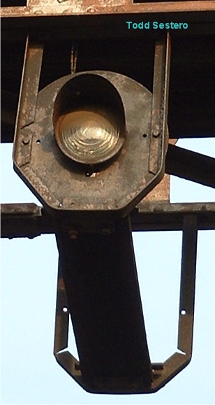
Below are the dimensions for a
typical single marker lamp with a standard background. This marker would
be used in the center position, top or bottom, and would have a white lens.
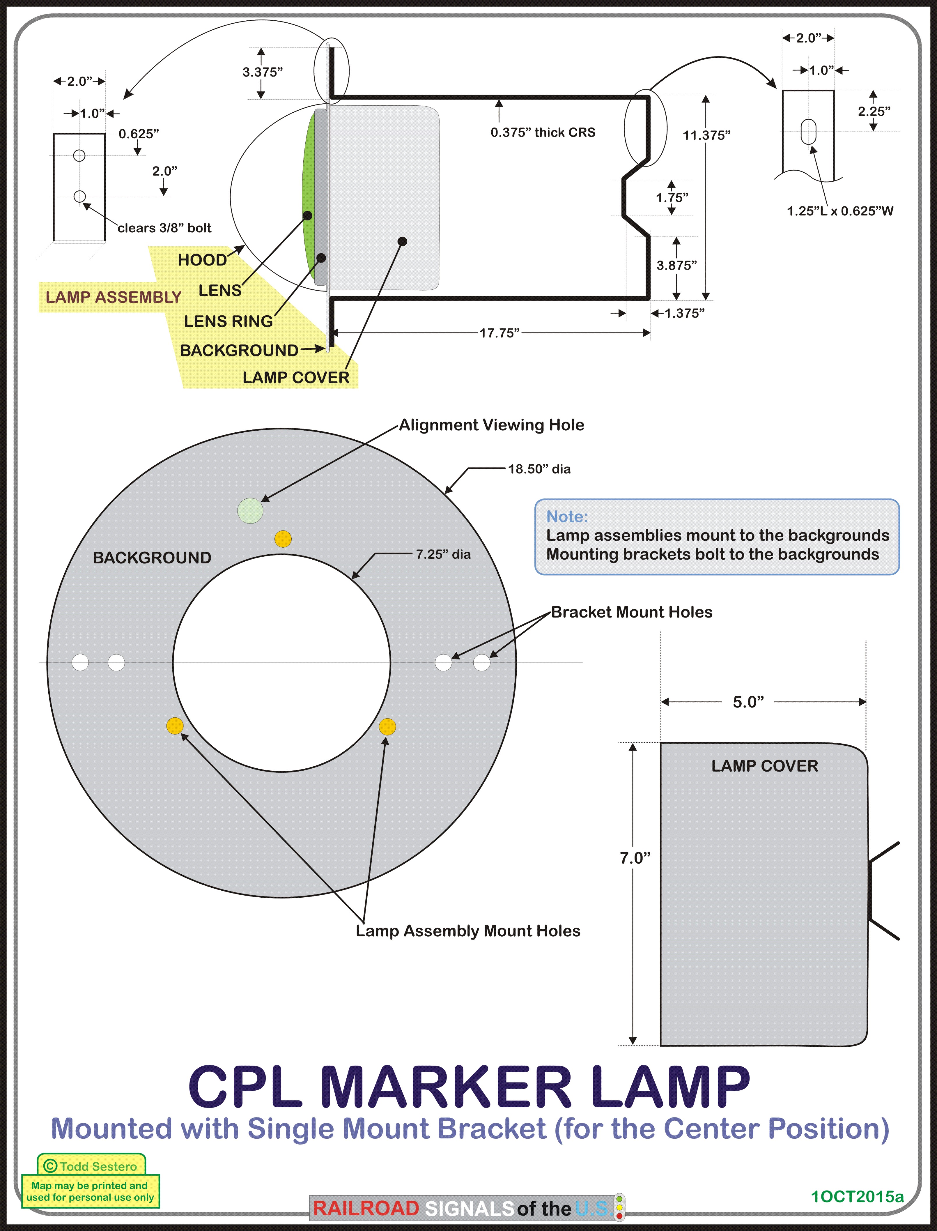
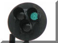
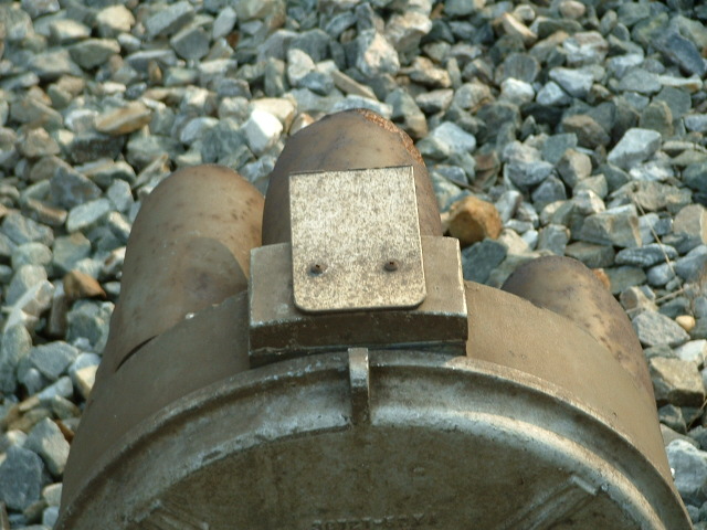
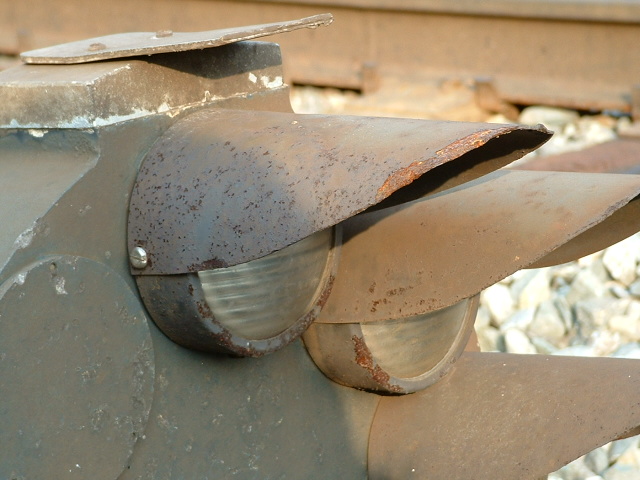
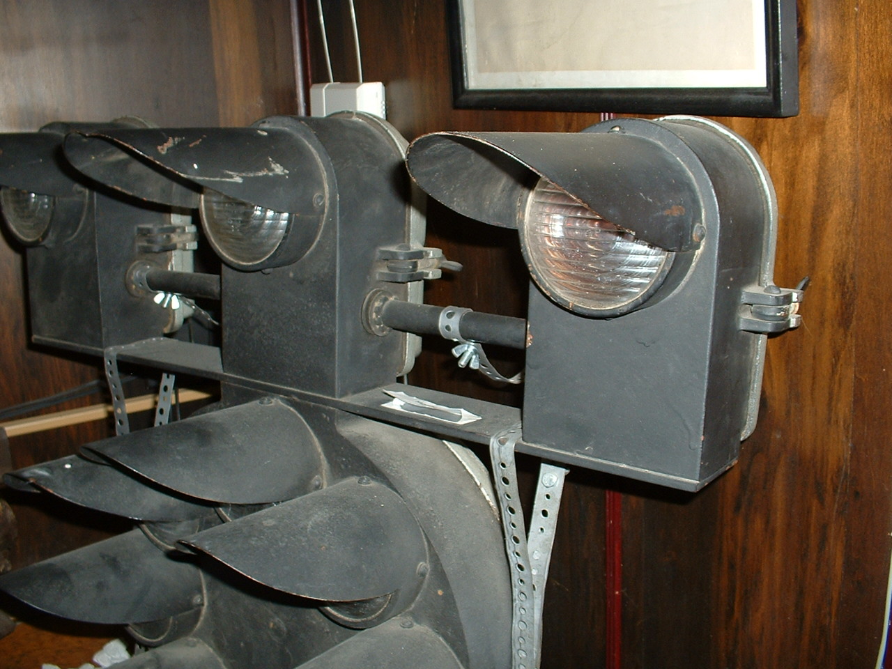
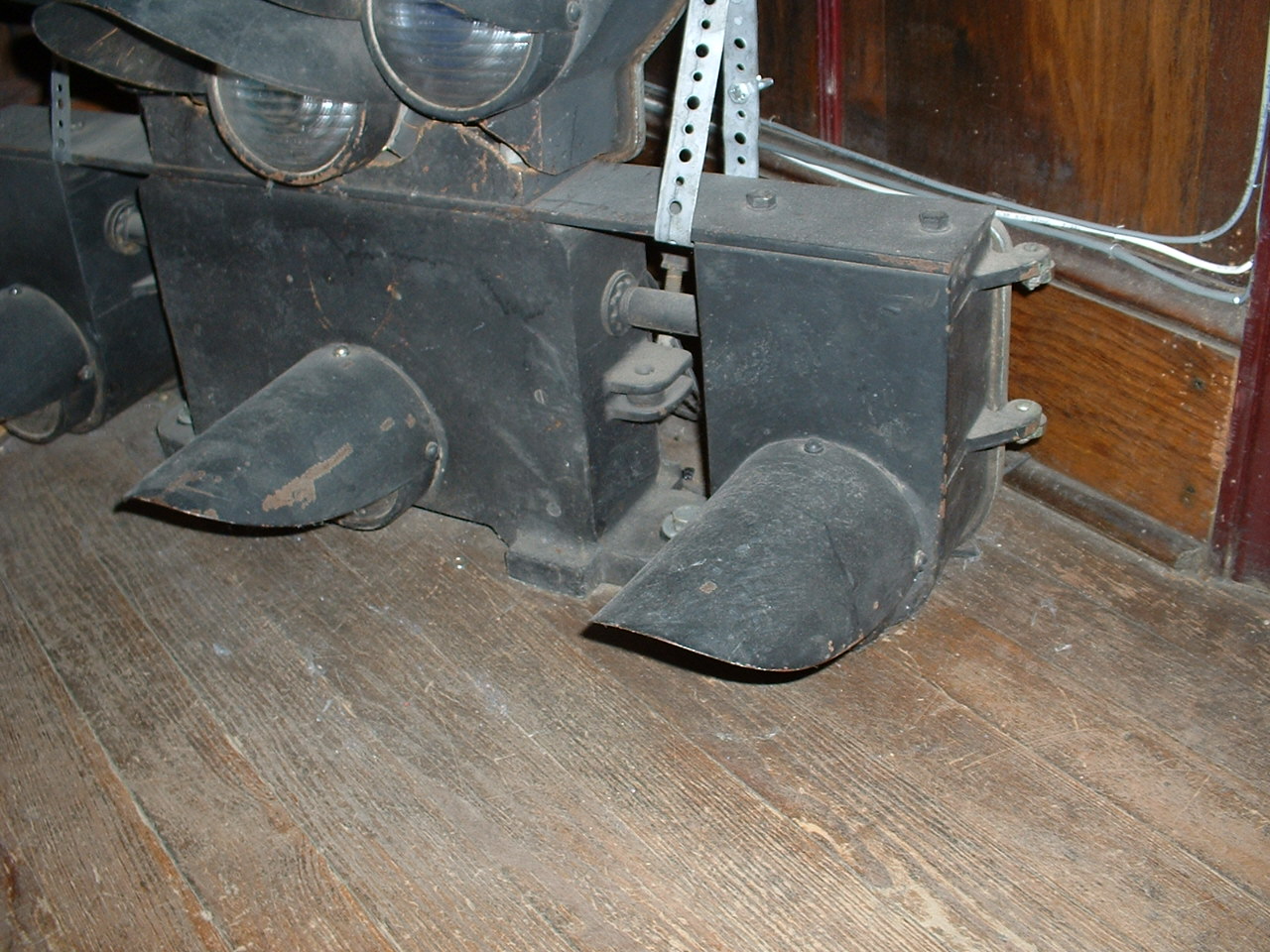
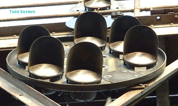
The lamp assemblies used on a CPL signal are pretty simple affairs. A single bulb, is focused by an inner colored fresnel lens, and an 8-3/4" (basically clear) outer lens. The outer lens for the white marker lamps are sometimes sand blasted on the inside . There is no reflector, which prevents false indications.
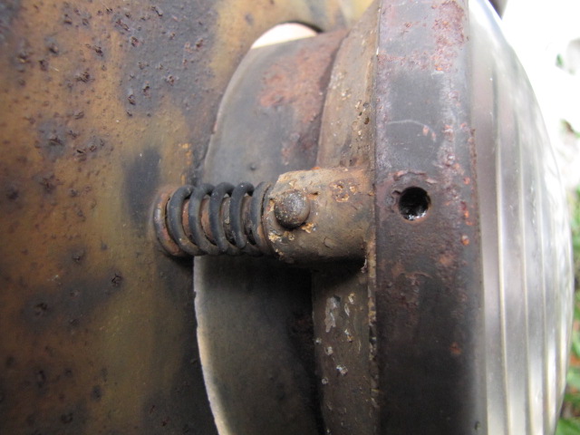
As seen below in the middle photo, the lamp assembly is mounted to the main head with three bolts, and uses springs to maintain their spacing from the background. By adjusting the nuts from the back side of the signal, the lamp could be aimed. Signal maintainers could look through an additional hole in the background for aiming purposes (above photo showing the cutout), viewing through a tang on the lamp assembly. The tang has a hole in it for aiming the lamp, which is clearly visible in the left photo below. The nuts used for adjusting the lamp, in later years, used ones with a nylon insert which did not require the use of a lockwasher.
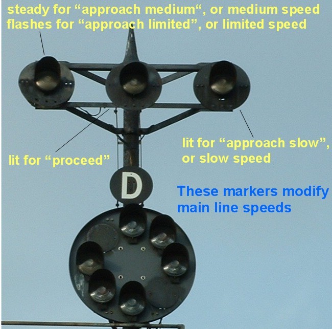
While CPL signals may seem a little intimidating at first, due to the number of lamps associated with it, the system is quite systematic, and simple to interpret once the "secrets" are known......
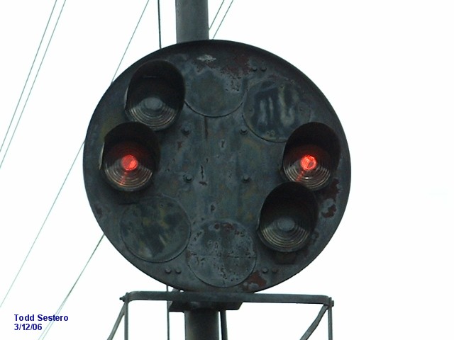
The first thing to know is that the main signal head can display clear (green), approach (yellow), stop (red), and restricting (lunar white), but they are ALL slow speed indications without using the marker lamps to modify the indication (so OK, STOP is not a speed :-) to a higher speed.
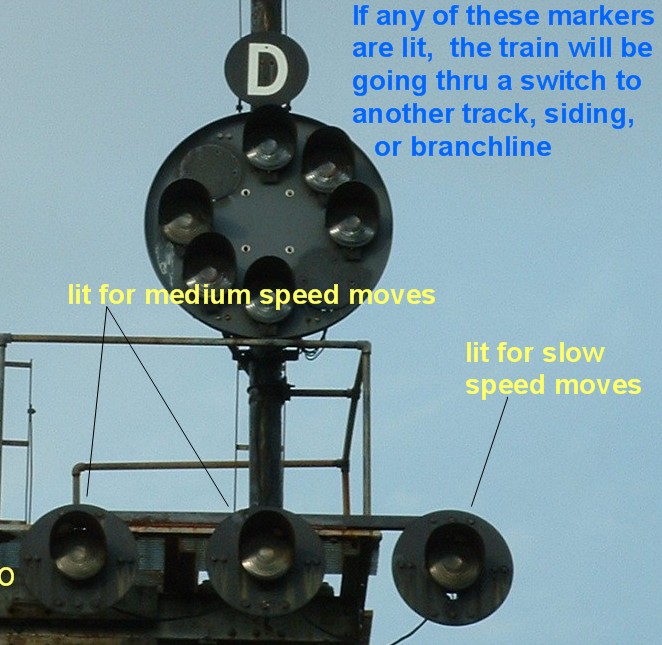
If any three of the lower marker lamps are lit, the signal is upgraded to a medium speed signal, telling the engineer he can pass THIS signal at medium speed.
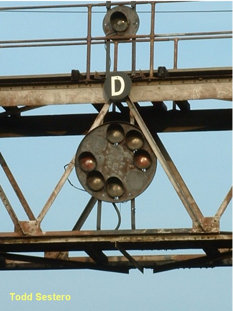
If any of the lamps on the top are lit, it is upgraded to a high speed signal for the block it controls, and he can pass THIS signal at normal speed: the maximum allowed by the timetable, rulebook, or indication. The photo below is showing a clear signal (rule 281).
If either of the two left hand white markers are lit, then the engineer needs to pass the NEXT signal at medium speed.
If either of the two yellow markers on the right are lit, he needs to pass the NEXT signal at slow speed.
CSX also uses flashing to upgrade the signal
in the following cases:
If the top left marker is flashing, the signal is upgraded
from approach medium (rule 282) to
approach limited. (rule 281B)
If the bottom center marker flashes, the signal goes from a
medium clear (rule 283) to a limited
clear (rule 281C) speed signal.
If the green lamps are flashing, the signal is upgraded from
slow approach slow (rule 287A, formerly rule
287), to slow clear (rule 287).
Current CSX speeds are below in Michael's section.
Michael Watnoski's
Primer
with help from
John V Engleman
B&O Color Position Light signals, CPL's, are the most complete signal system used today. This system is intuitive once you know the pattern. It also conveys more information than other signal systems. At the bottom of the page, is a drawing showing the components of a fully loaded CPL signal.
Another unusual feature of this signaling system, is that CPL dwarf signals are capable of displaying all the aspects of a high signal, not just slow speed aspects as most other systems.
Speeds referred to in the CSX rulebook, which this discussion is based on, are as follows: Limited - 45mph, Medium - 30mph, and Slow - 20mph. Some of you may raise an eyebrow at the slow speed. Yes, it was changed from 15!
An almost full CPL signal in south Baltimore
The main head displays the track occupancy for the selected route. The B&O only used a two block system. If the next two blocks beyond the signal were were clear (not occupied), the main head displayed a "high green" for "proceed". When the second block was occupied, the head displayed yellow for "approach", preparing to stop at the next signal. Trains exceeding medium speed were required to slow to that speed. If the block ahead of you was occupied, the signal displayed red for stop.
If the signal was an automatic, having a
number board, then this was regarded as stop and
proceed in the B&O days, and is now (under CSX), a
restricted proceed.
Stop and proceed allowed the train to move,
after stopping, at restricted speed (not exceeding 15 mph), prepared to stop
within half the distance of sight, while watching for stopped trains, broken
rail, or misaligned switches. If the route is set for an un-signaled track, the
restricting aspect, left diagonal lunar white lights, is used. This requires
the train to travel at restricted speed, as above.
The other six lights, or
marker
lamps, refer to the speed rating of the route being taken immediately beyond the
signal and/or at the next signal. As shown below in the "large" drawing, the left and middle markers are
white, the right markers are
yellow.
CPL signals, BTW, are the only signals in the United States that employ white lenses in their aspect.
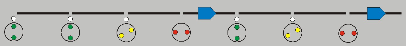
No Marker Lamps
For a CPL signal with no marker lamps lit, the indications are slow signals as seen below, except for STOP. The use of marker lamps modifies these meanings. Without any light above or below the main head, the train is going thru switches at slow speed, and must limit speed to 15 mph until the entire train is over the switches. The three rules without markers lamps fall low in priority except for red, which is "at the bottom":
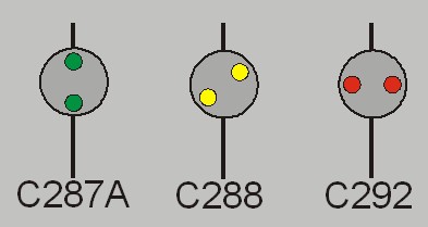
1) green
for rule C-287A, slow clear
2) yellow, rule C-288,
slow approach
3) red for rule C-292,
which is stop
Upper Row Markers
Any marker above the main head indicates that route is going to be the main or high speed route beyond this signal. This allows the train to proceed at track speed on green signals, as posted in the employee timetable for the territory.
Add a white marker to the left, and it tells the engineer to reduce the train to medium speed to approach the next signal.
If the yellow marker on the right is lit, then he needs to slow down and approach the next signal no faster than slow speed.
Bottom Row Markers
If we add markers below the main head, they are all variations of medium speed moves.
If we add a middle white marker, we have rule 283, Medium Clear, which states the train can proceed at medium speed through the interlocking or whatever comes after the signal.... the block ahead is clear.
If we add a left marker, that gives us rule 283A - Medium Approach Medium, which states the engineer can proceed at medium speed, and upon seeing the nedst signal, approach it at medium speed.
If we light up the yellow marker on the right, the engineer can proceed at a medium speed till he sees the next signal, and once seeing it, must approach it at slow speed.
Yellow and Red Aspects
These aspects are in addition to the "plain" indications mentioned above, in other words, the main signal head without a marker lamp lit.
There are two yellow aspects with a marker, and one red..... all use the middle marker.
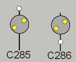
Rule C-285 is approach, preparing to stop at the next signal. Rule C-286 is medium approach.... medium speed thru turnouts, etc, then proceed prepared to stop at the next signal.
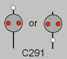
The red aspect with a marker is rule C-291, restricted proceed, which the indication is the same for a restricting aspect - proceed at restricted speed. It has two variations, as shown. Many of you may be familiar with this aspect being called stop and proceed. John adds, "during the gas shortage of the early to mid 70's, the B&O needed a way to to reduce costs, so they changed the rule to allow trains to keep rolling, looking for trains or problems ahead at no more than restricted speed".
Other CPL Details
Rules 287A and 288 fall next to each other in priority, the only difference being 287A specifies going at slow speed to approach the next signal, while 288 says to prepare to stop at the next signal, but does not give a speed once thru the turnout. Both mandate going at slow speed thru the turnout.
 If
lit, the row of markers below the main head indicates that train will be routed
over switches at medium speed. The train must reduce to
medium speed, 30 mph, until all of it is passed through the switches,
then it can proceed at the track speed set by the signal. This is the typical
indication when changing tracks at a crossover.
If
lit, the row of markers below the main head indicates that train will be routed
over switches at medium speed. The train must reduce to
medium speed, 30 mph, until all of it is passed through the switches,
then it can proceed at the track speed set by the signal. This is the typical
indication when changing tracks at a crossover.
Use of the lower markers specifies two
speeds for the train. One is the speed thru the turnout, which as stated above,
is medium speed. The other speed referenced is the speed of the
train tha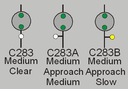 t
is authorized once the entire train has cleared the turnout. The speeds show up
in the name of the aspect, such as: medium-approach
slow or medium-approach medium.
The left marker signifies medium speed, the right marker
slow, and the middle marker is unspecified (the rule just says "then
proceed".
t
is authorized once the entire train has cleared the turnout. The speeds show up
in the name of the aspect, such as: medium-approach
slow or medium-approach medium.
The left marker signifies medium speed, the right marker
slow, and the middle marker is unspecified (the rule just says "then
proceed".
Flashing Aspects
CSX employs three flashing aspects, rules C-281B, approach limited; C-281C, limited clear; and C-287, slow clear. The first two had flashing markers, 287 used a flashing green aspect without any markers. It's interesting to note, if you look at the old (B&O) versus the new (CSX) rulebooks, that the B&O did not employ flashing aspects.
CSX also slipped a new aspect in the books with the flashing green of rule C-287 (slow clear). The solid green aspect that was formerly rule C-287, slow-approach slow, is now rule C-287A.
Using Triangle Signs
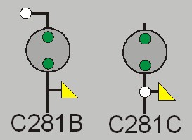
The two rules above, C281B (approach limited) and C281C (limited clear), could employ one of two methods to indicate the aspect. One option is to use a flashing marker (without the yellow triangle), and the other is to use a steady marker, with a yellow triangle sign.
Rule 281B was previously rule C-282 under the B&O, and what is now 282, was 282A. It's all very confusing!
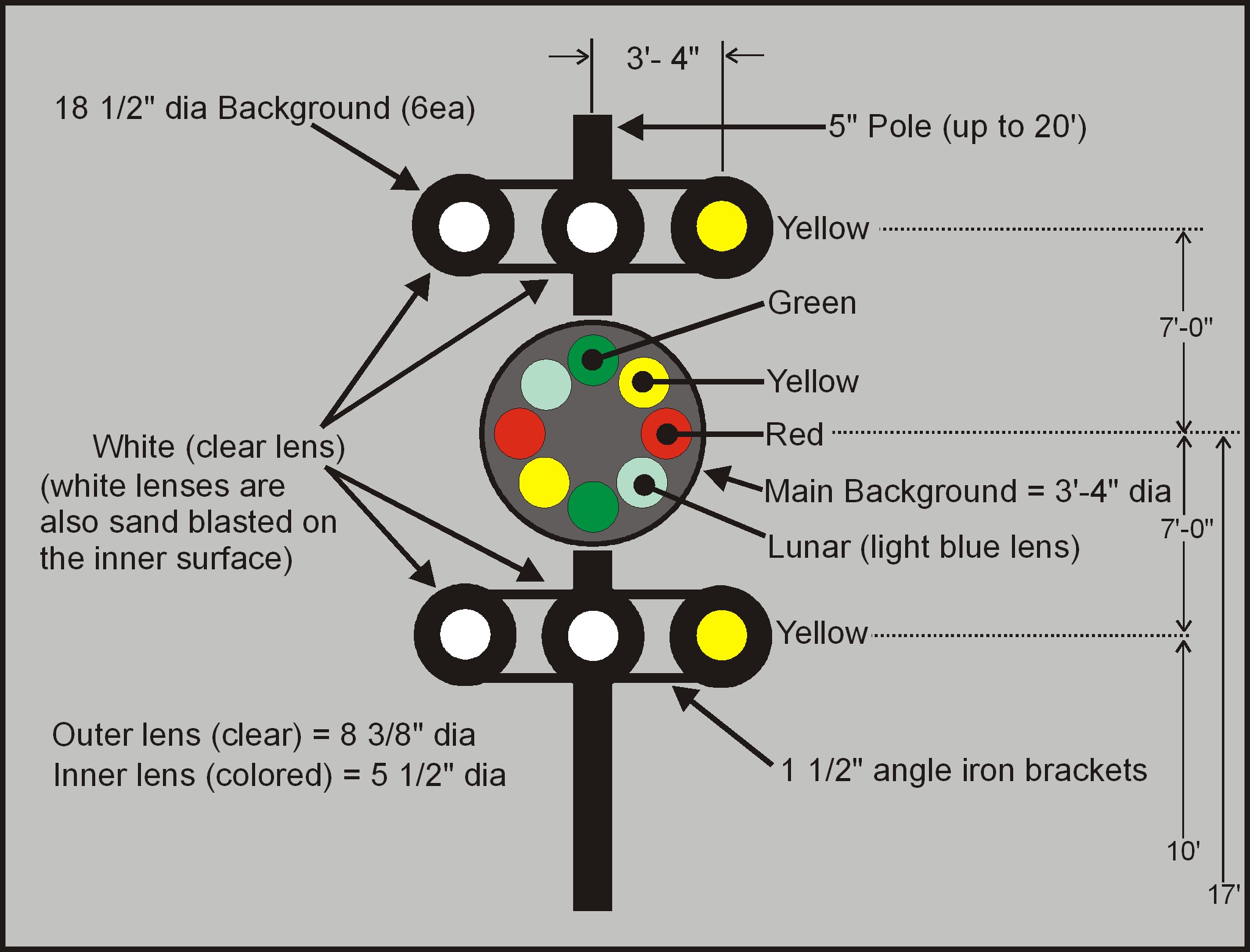
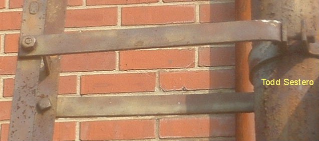
This Drawing shows the major components of a full size B&O CPL signal. As seen in the photos above, if left and/or right marker lamps are used, there are also two pieces of angle iron used to stabilize each marker, going from the marker to the pole, in addition to the cross pieces shown above. A single 5" pole is used up to a height of 20 feet, above that, the pole starts out as a 6" pole at the bottom, and then reduces to 5". Refer to the US&S drawings on another page.
John Engleman formerly worked for the B&O as an engineer (also for the Pennsy for a while prior to that, and was qualified on both). His inputs have been invaluable in navigating thru some of the signal "urban legends" (and has some good stories to boot!).
Graphics and Pictures by Todd Sestero
Click Here for this in PDF format
the CPL pages from a 1935 US&S catalog.
Other CPL and CPL related Info Pages
http://www.alkrug.vcn.com/rrfacts/signals/ColorPosition/sigrules_BO.htm
Good CPL info by A A Krug
http://www.alkrug.vcn.com/rrfacts/signals/signals.htm
Additional signal info by A A Krug
http://www.cg-tower.com/cpl/
Good CPL signal info by Eric
http://www.navpooh.com/sigpics.html
Good CPL signal info by Mike
http://mtnsub.org/features/cpl.html
Good stuff on the B&O way out Western Maryland way by
Markolf
Gudjons
B&O Color Position Light Signal
http://www.jdtower.org/History.htm
http://www.trainweb.org/oldmainline/oml7a.htm
http://en.wikipedia.org/wiki/North_American_railroad_signals
http://www.borhs.org/Archives/cplcontent.html
Drawings for model railroaders by Michael Watnoski
SIGNAL VARIATIONS
Main Head Variations
Marker Lamp Variations
Mounting
Variations
Dwarf CPL’s
The pictures below show variations in the indications the main CPL head can display.

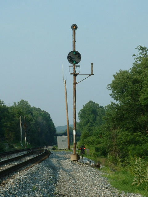
CPL signal with only one marker, giving us the highest speed available when the marker lamp is lit.
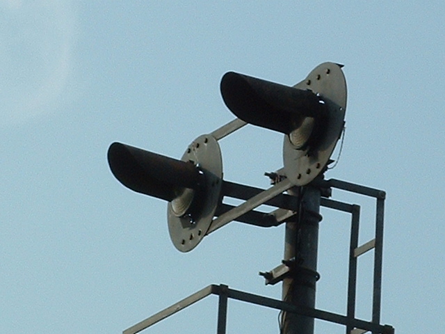
Two marker lamps.... Left is south of Bush St, right is at
Ridgely St, Baltimore. As of November 2013, new colorlight signals are
being erected.
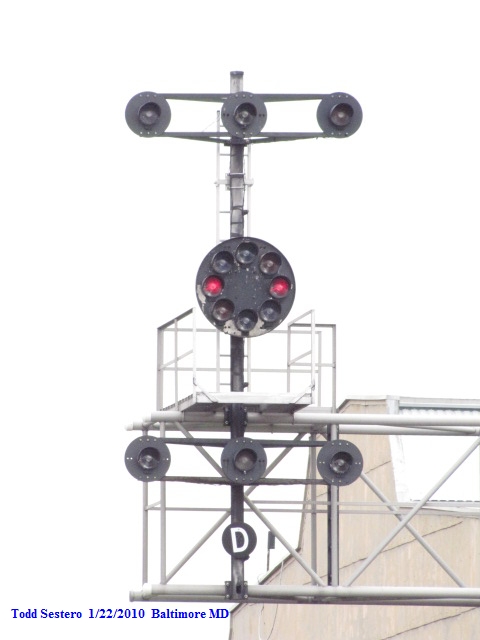
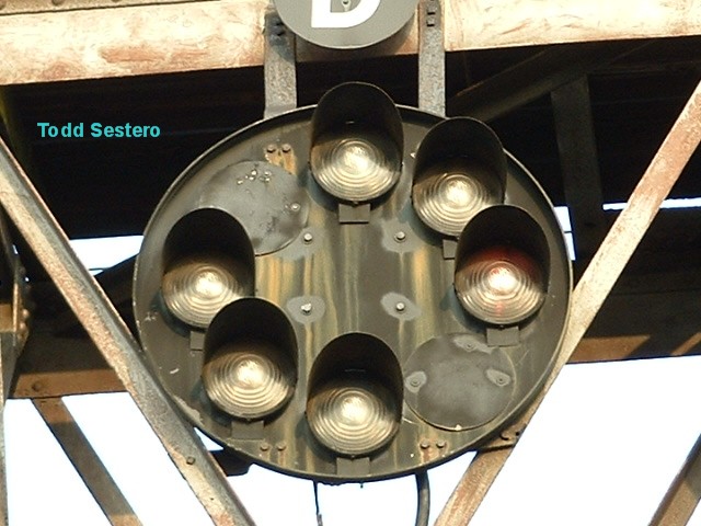
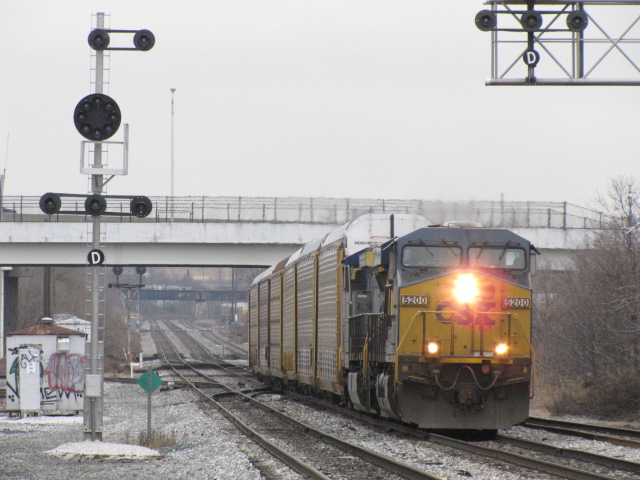
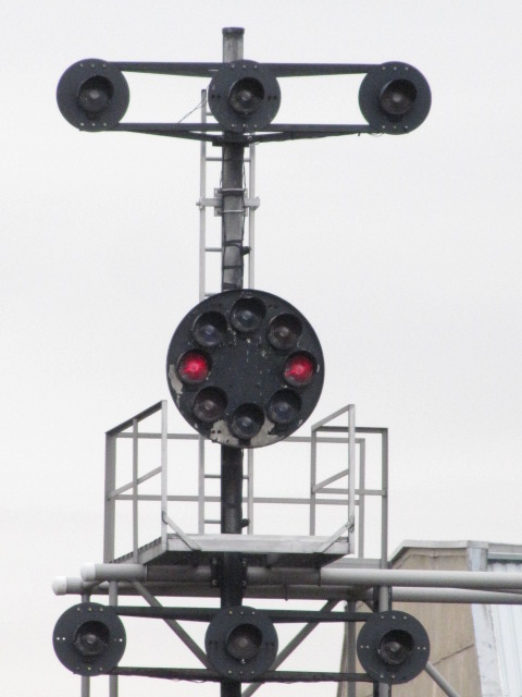
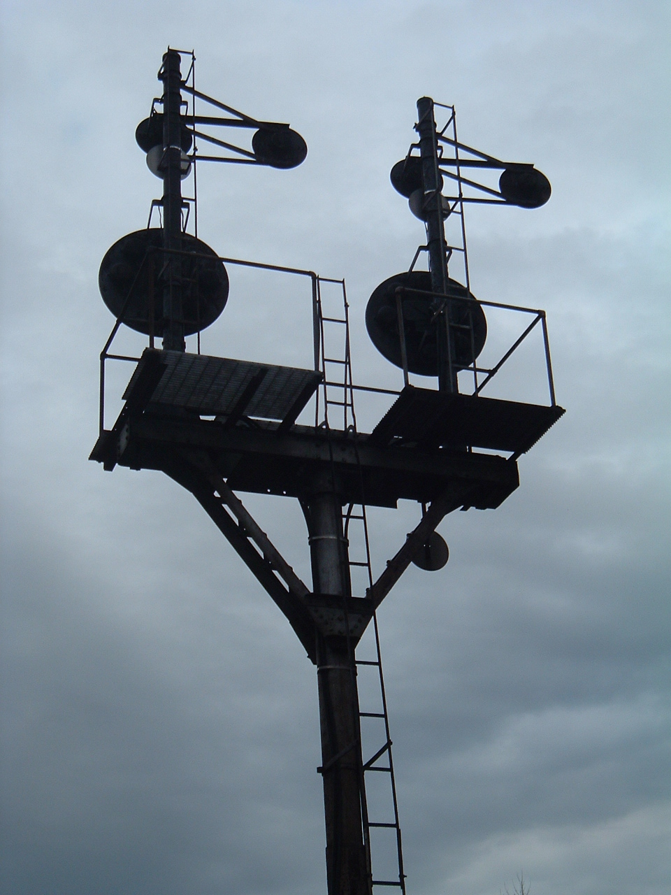
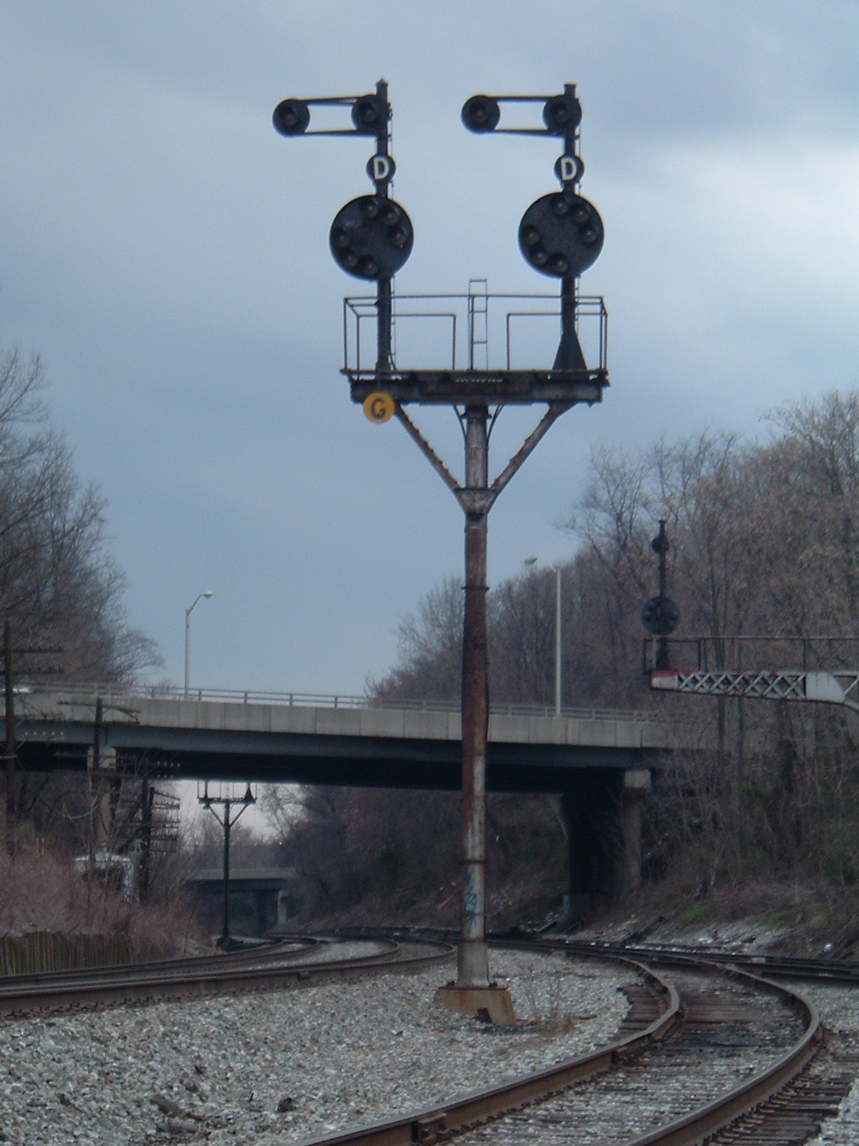
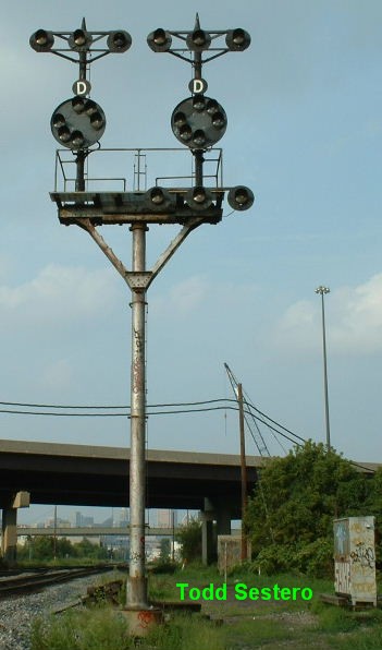
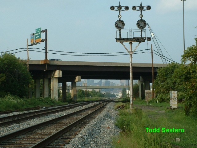
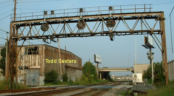
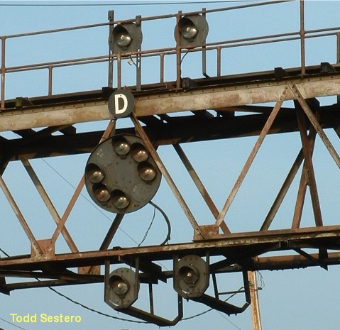
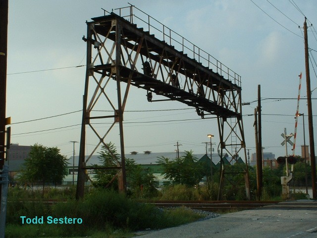
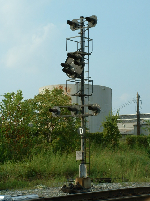
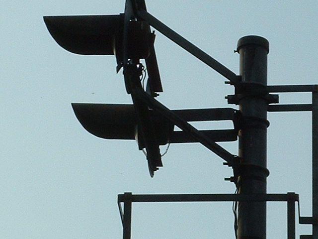
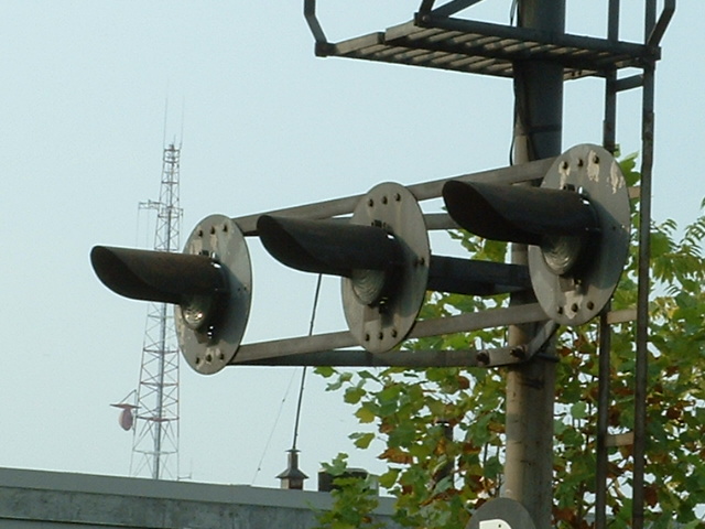
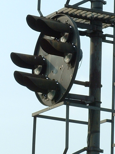
Three markers above, the left of two signals shown on the bracket post
below. This signal was replaced with colorlights in 2012.

Four markers on a signal bridge in Baltimore, slightly west of
Baileys wye at Ridgely St for NB traffic.... In the middle is one at the Dorsey
MARC station for SB traffic to DC showing approach (replaced with colorlights in
early 2012), and finally on the right, a CPL on the north
point of Baileys Wye for SB traffic to DC displaying a medium clear.

Five marker lamps.... almost full.... The one on the
left is south of Bush St. in Baltimore for NB trains, the one on the right is
almost directly across the mainline at the same location for SB trains.
All of these signals at Carrolls Interlocking are now gone.
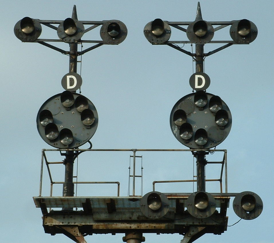
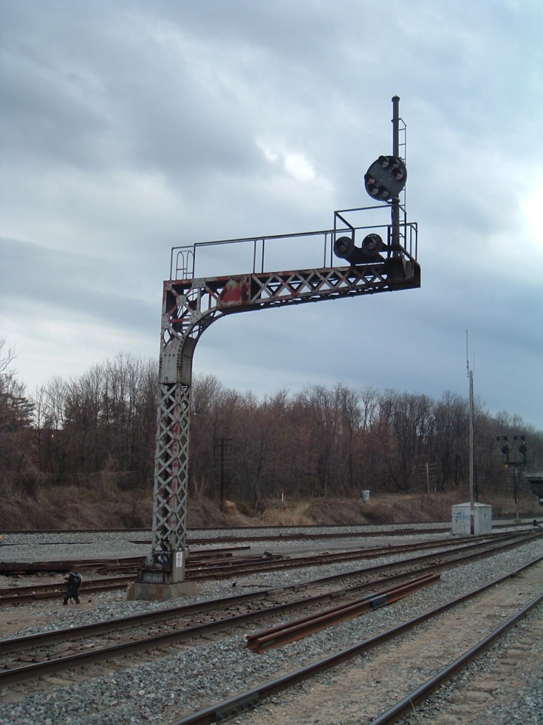
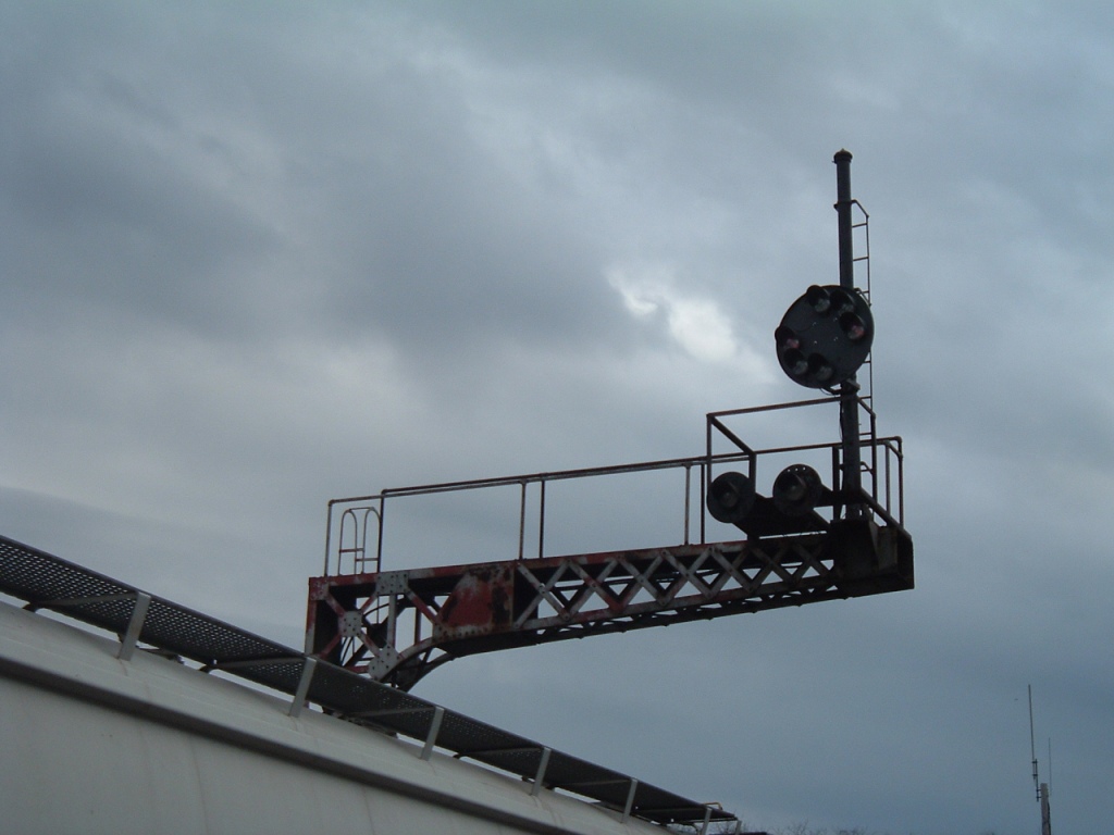
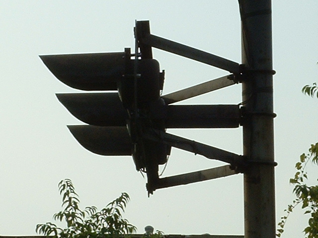
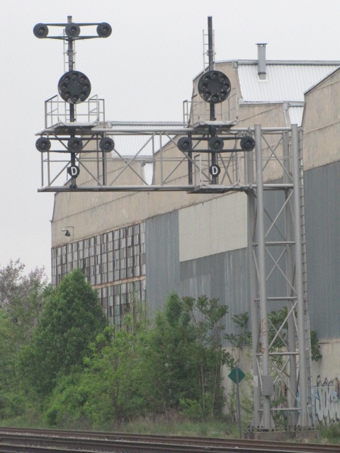
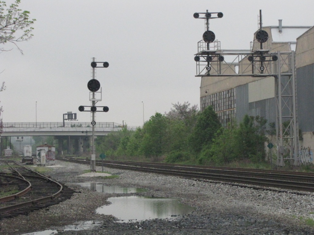
A three marker CPL and a six marker CPL share this bracket
post installation south of Bush St in Baltimore for NB traffic,
In the right photo, which is about a quarter mile north of the signal on the left, and a few hundred feet south of Bush St, is a "brand new" full CPL.
We thank CSX, for the time being, in not upgrading this interlocking to colorlight signals..... get em while you can folks!!!
CPL signals can be mounted in a variety of ways. They can be mast, or pole mounted, they can be mounted on signal bridges, and they can be mounted on bracket posts. Unlike Pennsy PL signals, I have yet to see a CPL signal mounted on top of a relay or equipment case.

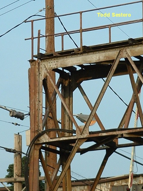
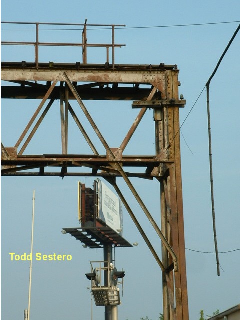
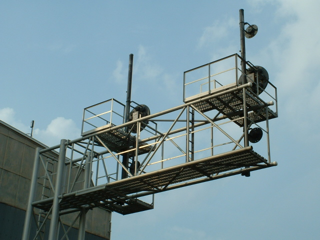
A typical B&O signal bridge, located off of Bailey's Wye to
the south, in Baltimore.
CPL signals on a cantilever bridge. The two on the left
are at the south end of Winans yard in Baltimore, and were replaced by
colorlights ~2009. The right two photos are courtesy Eric Davis.
On the left is a traditional B&O mast mounted signal, on the
right is one mounted on a newer aluminum mast.
Typical bracket post installation at the south end of Winans
yard / Baltimore.
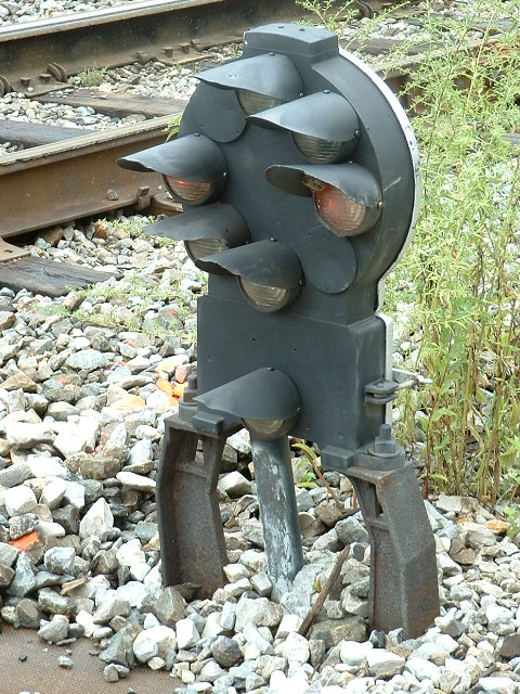
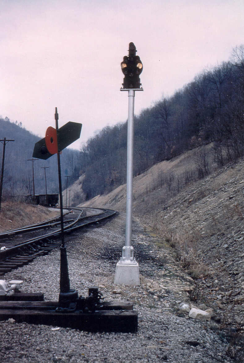
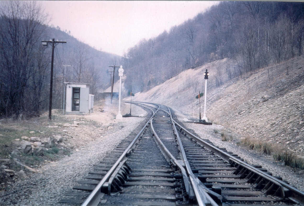
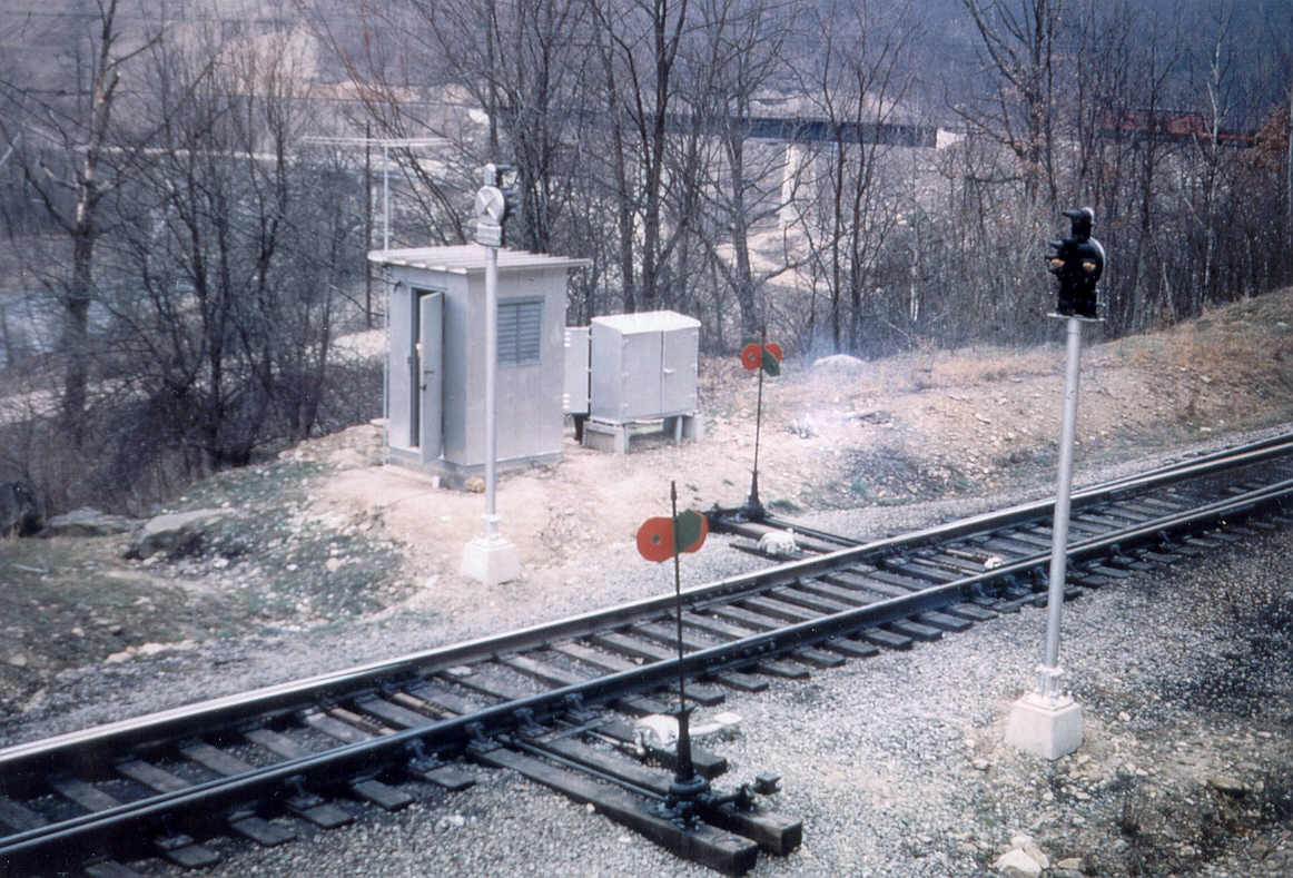
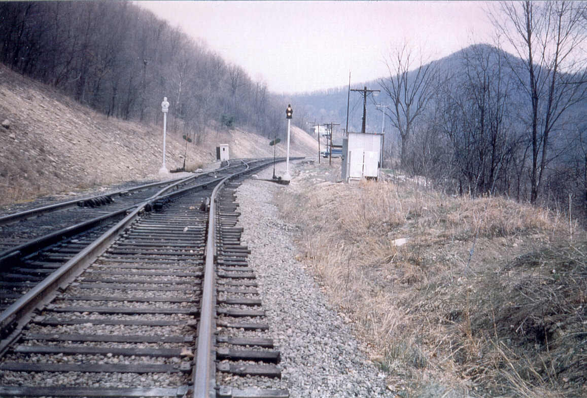
Dwarf CPL signals are normally mounted at ground level, or close to ground level. There are a few exceptions, the most notable one is probably the use of dwarf signals in the northern approach to Union Station in Washington DC, where they decided to replace the semaphores that used to be in service there with the B&O dwarfs. One other example is an experiment the B&O tried back in the early 60's, where they mounted dwarf signals on top of 10 foot mast for controlling trains by remote control - pictures below.
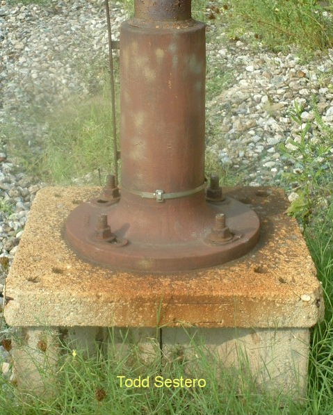
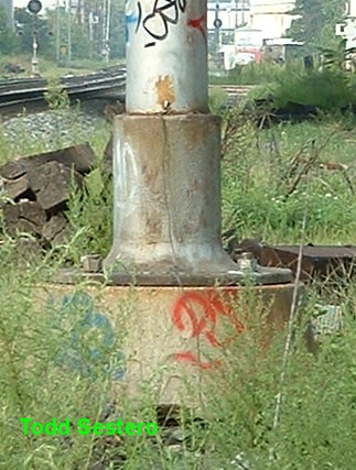
Here is a dwarf signal mounted to a steel plate which is
secured to the bolts at the base of the mast. It saves installing a
separate base for the dwarf. The B&O used this in most locations where
signals were placed at the end of a siding. Also notice the doll post,
telling the engineer the high signal controls the track to left, the doll post
is a place holder for the siding.


A three aspect dwarf in South Baltimore.

A three aspect dwarf at Bailey's Wye in Baltimore, with one
marker lamp.
A two aspect dwarf in Brunswick MD.
A full four aspect dwarf with two upper markers, also in
Brunswick MD.
A full dwarf with all six markers at the Brunswick MD Railroad
Museum.
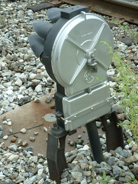
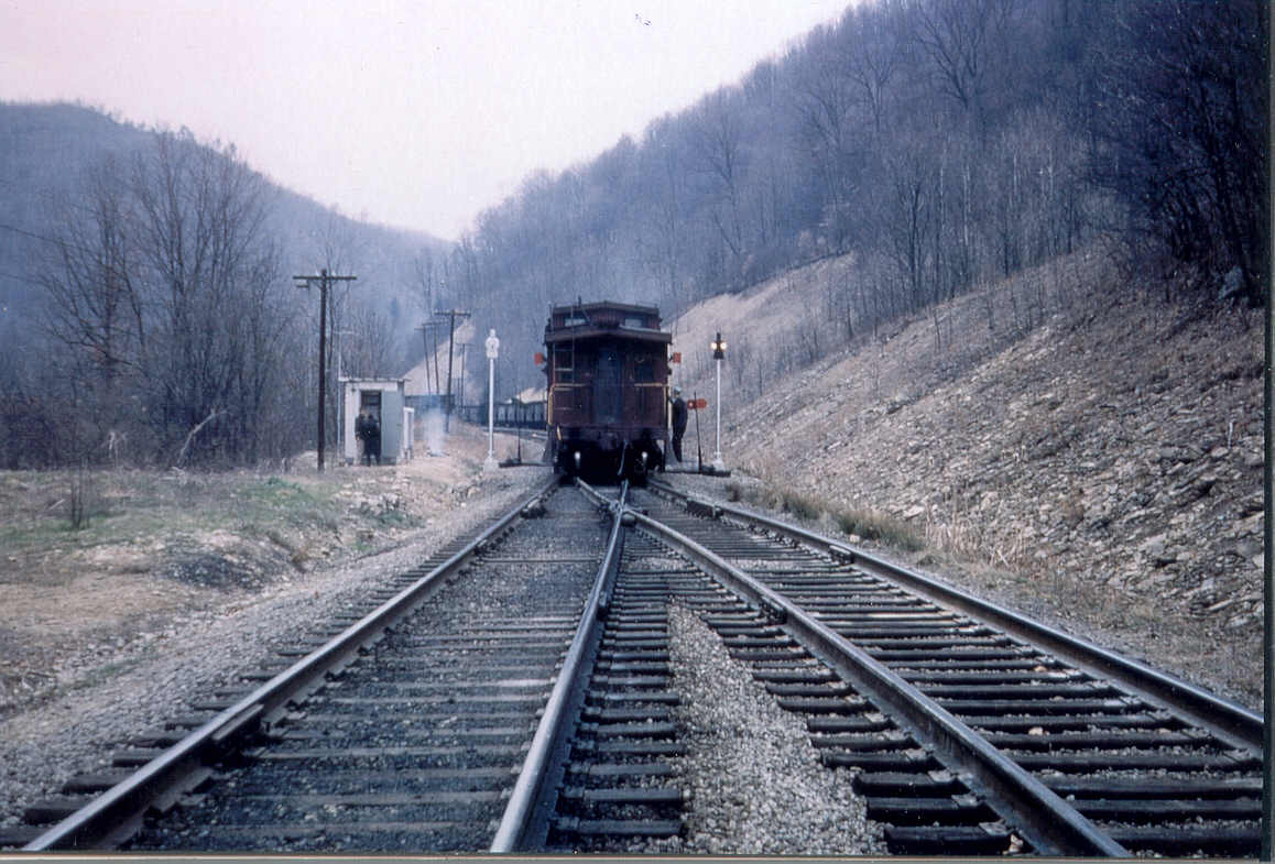
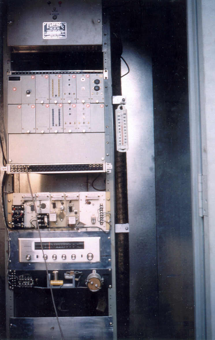
Below are pictures of another example of using dwarf CPL's, this time for a non-standard use. Back in the early 60's, the B&O tried to implement radio control of the signals on a manual block section after a fatal accident occurred. They put dwarf CPL's up on the top of 10 or 12 foot tall poles, and re-lensed the signal so all of the aspects were yellow, like the Pennsy PL's are all single colored white. If you have the July 2004 issue of Trains, you can look for the story by Harold E. Meeker starting on page 50. Photos are used with the kind permission of Mr. Meeker, who is a most interesting fellow to talk to and has a rich railroad history and background, and if you are into coincidences, he lived about 5 miles away from me when we first moved into the Towson area of Baltimore back in 1966 while he was working for the B&O!! If you go looking for these signals, forget it, as they were removed shortly after the experiment ended. A bonus photo he sent me, and not in the article, is the one to the right of the equipment used in the test, an application using what we call today "COTS", or, Commercial Off The Shelf.
GM&O CPL's
Gaithersburg MD
Baltimore MD - Westport
Baltimore MD - Under I95
Baltimore MD - Ridgely St
Baltimore MD - Below Bush St 1
Baltimore MD - Below Bush St 2
Baltimore MD - Washington Blvd
If you are out and
about chasing CPL signals, here are a few of my guides for areas that contain
CPL's:
Baltimore MD
Deshler OH
Fostoria OH
Perryville MD
Washington DC's Union Station
CPL Signals north of Baltimore

These pictures are courtesy Daniel Dawdy, and are from the Yahoo Railway Signaling group's file section. To see more, you'll need to join. Daniel also has a website and designs WebPages.

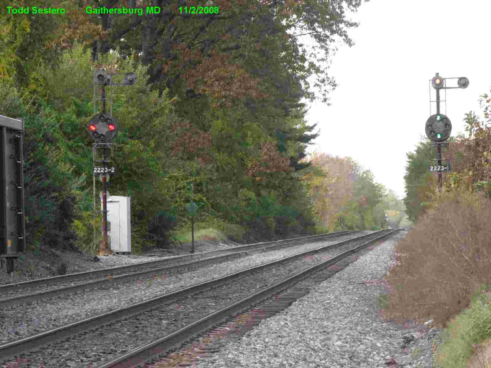
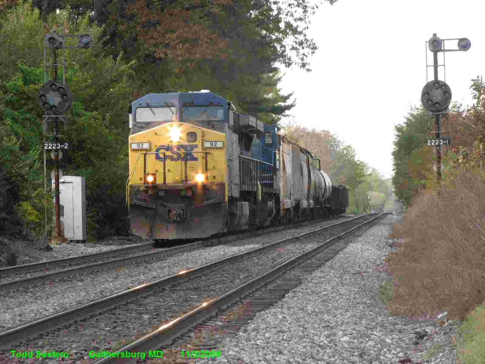
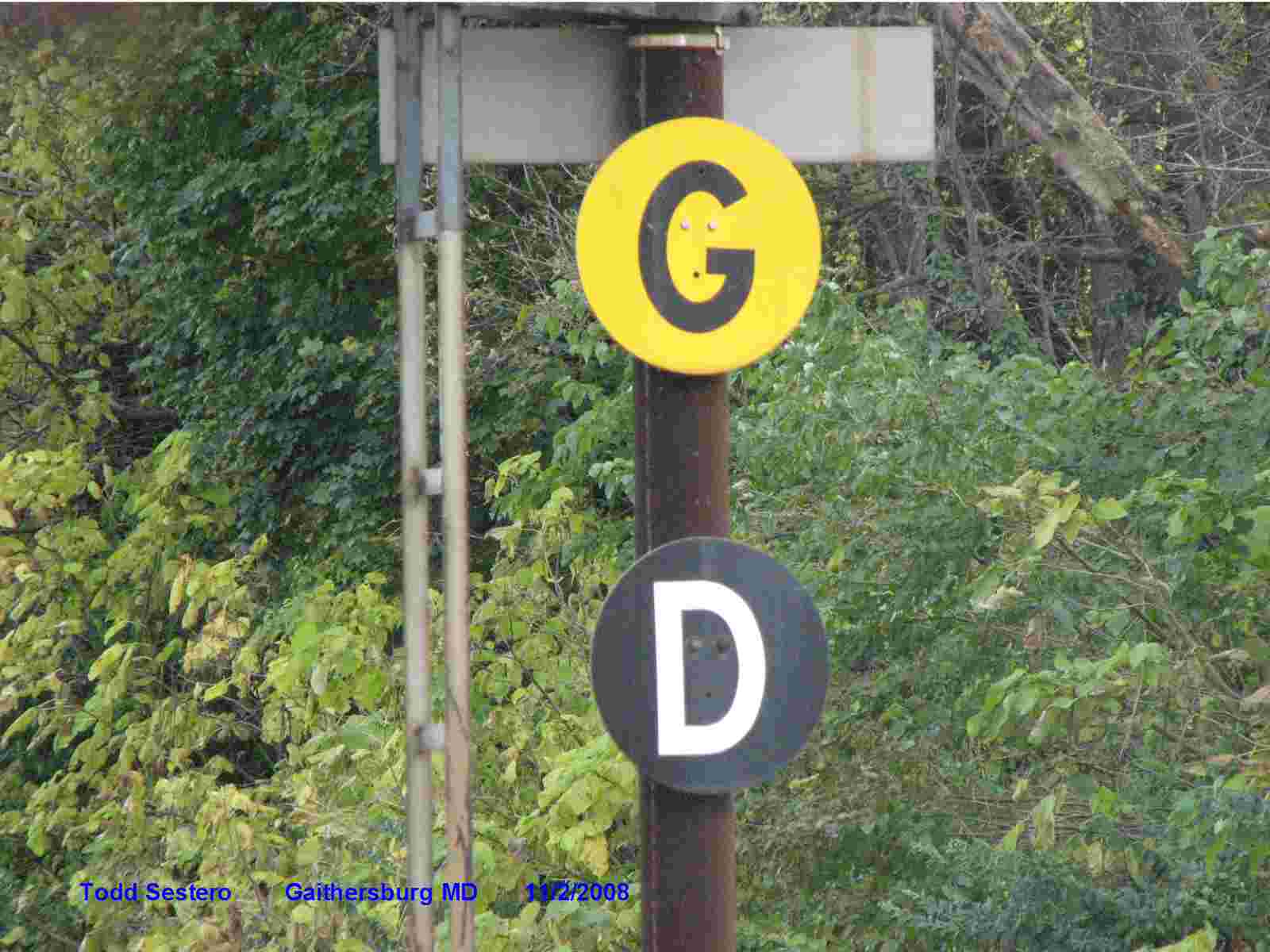

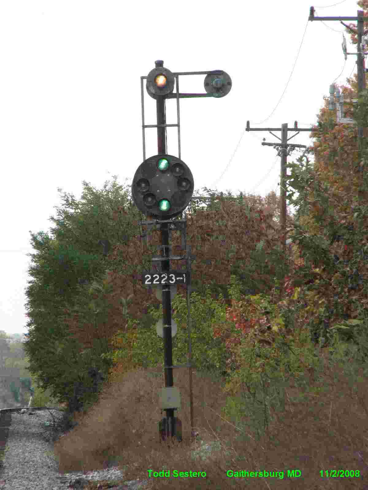
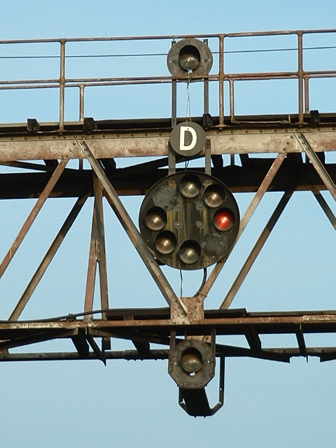
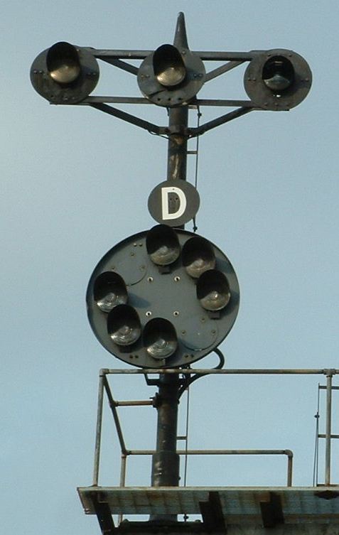
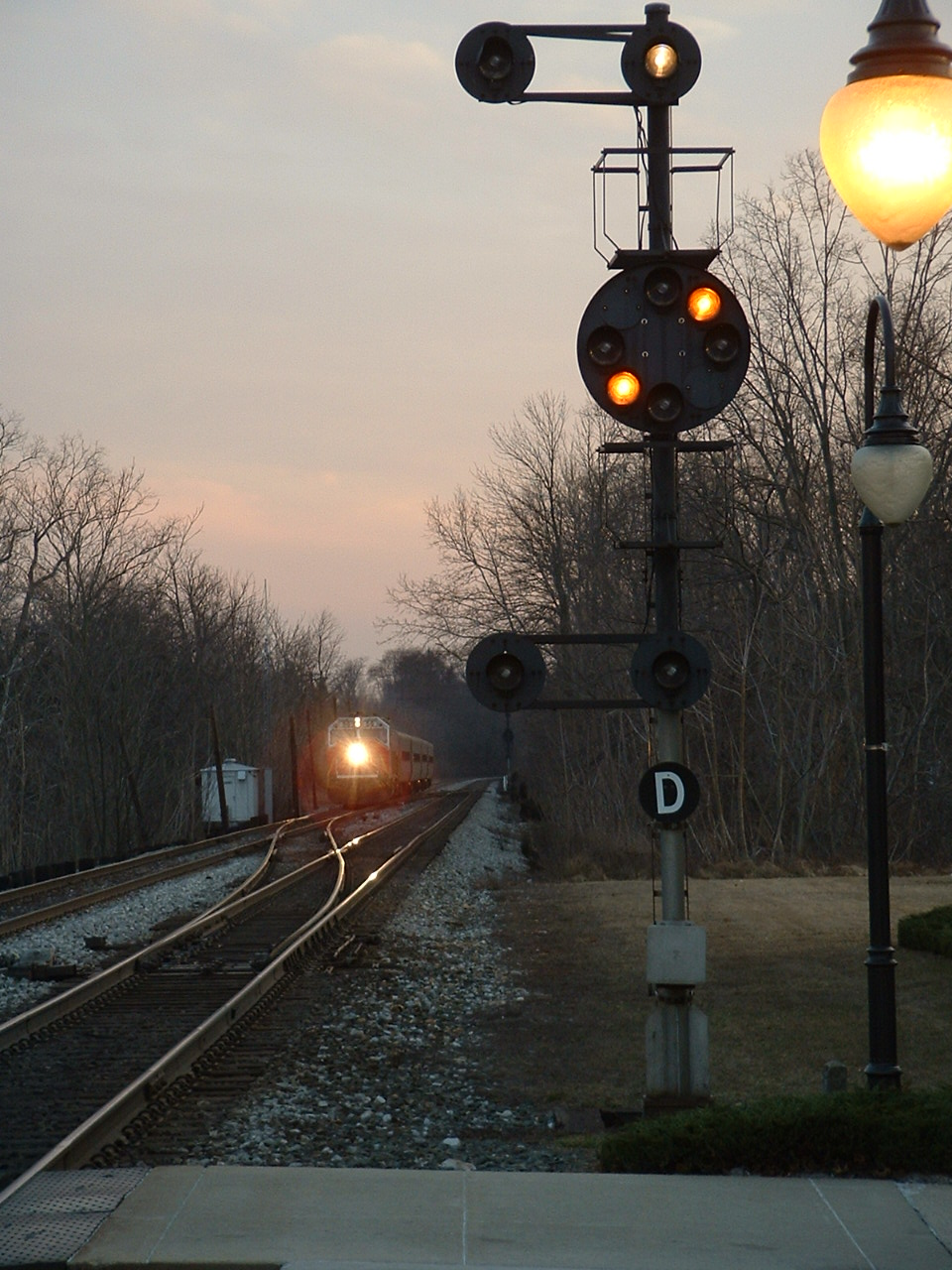
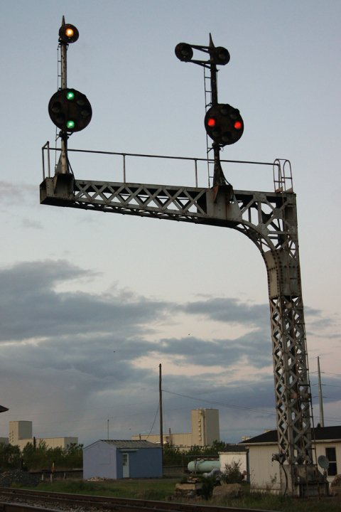
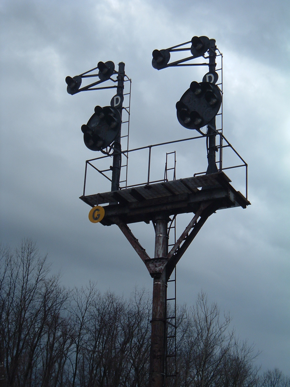
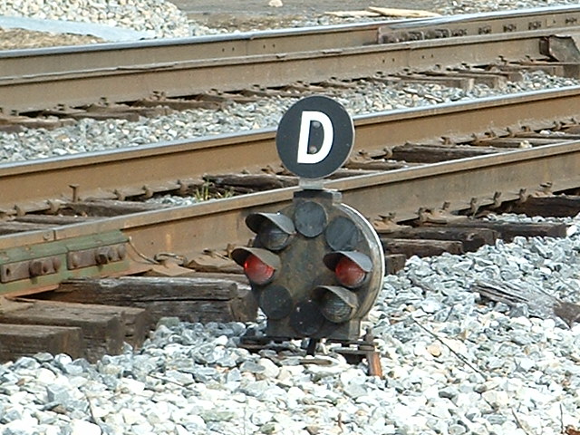
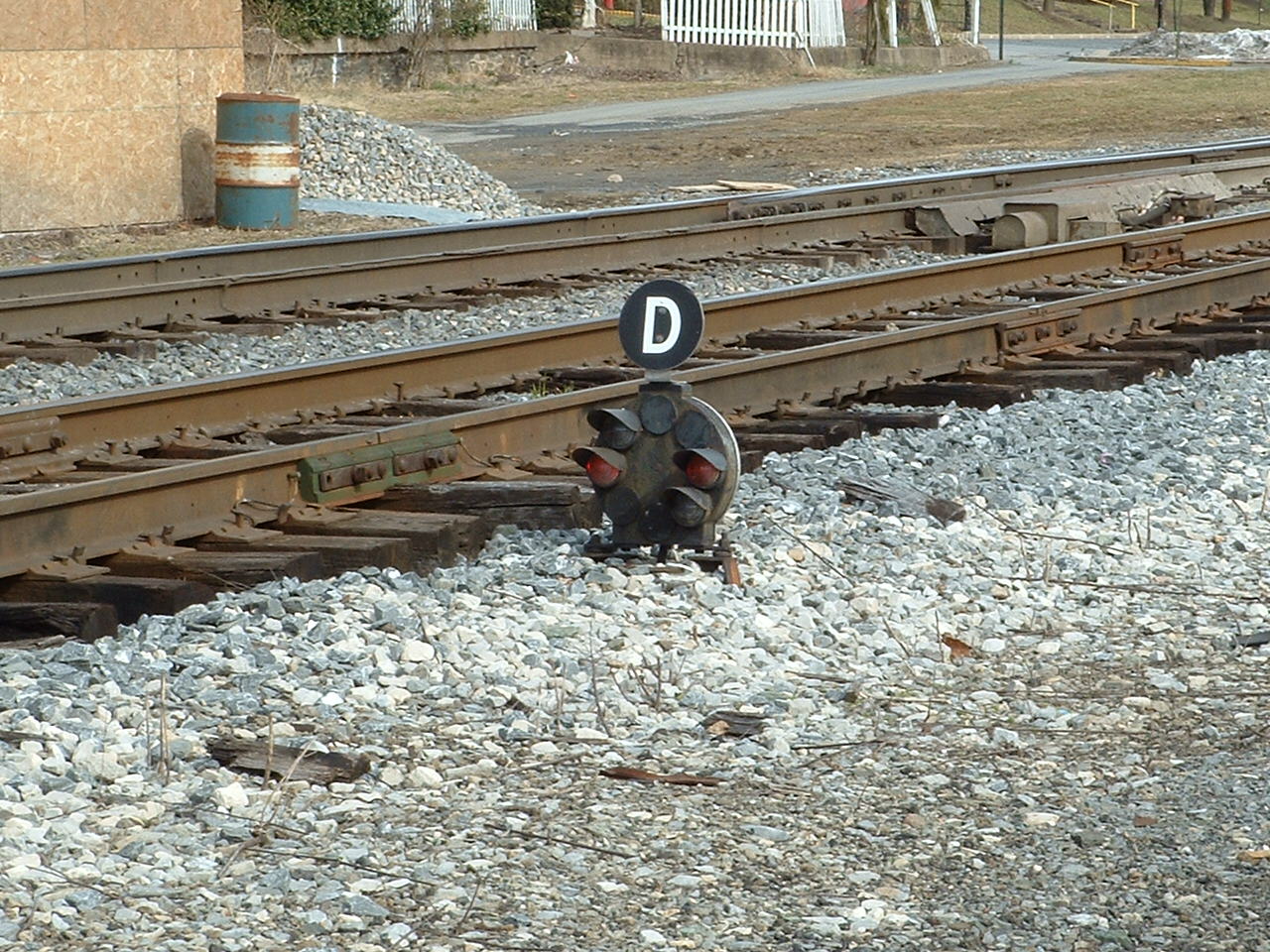
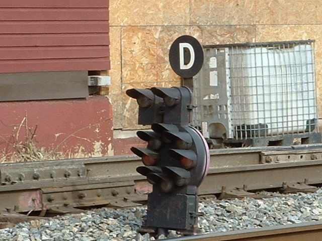
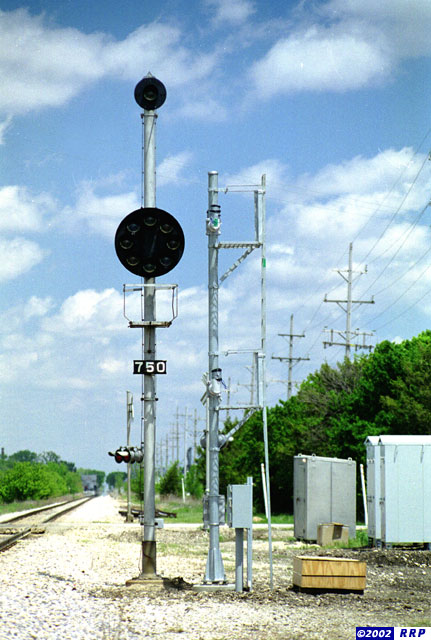
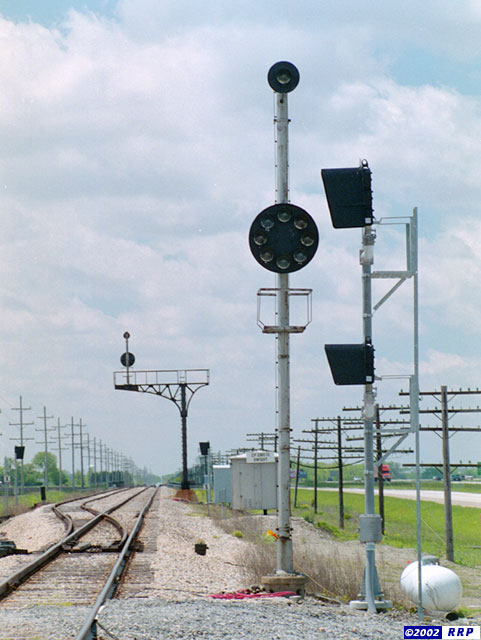
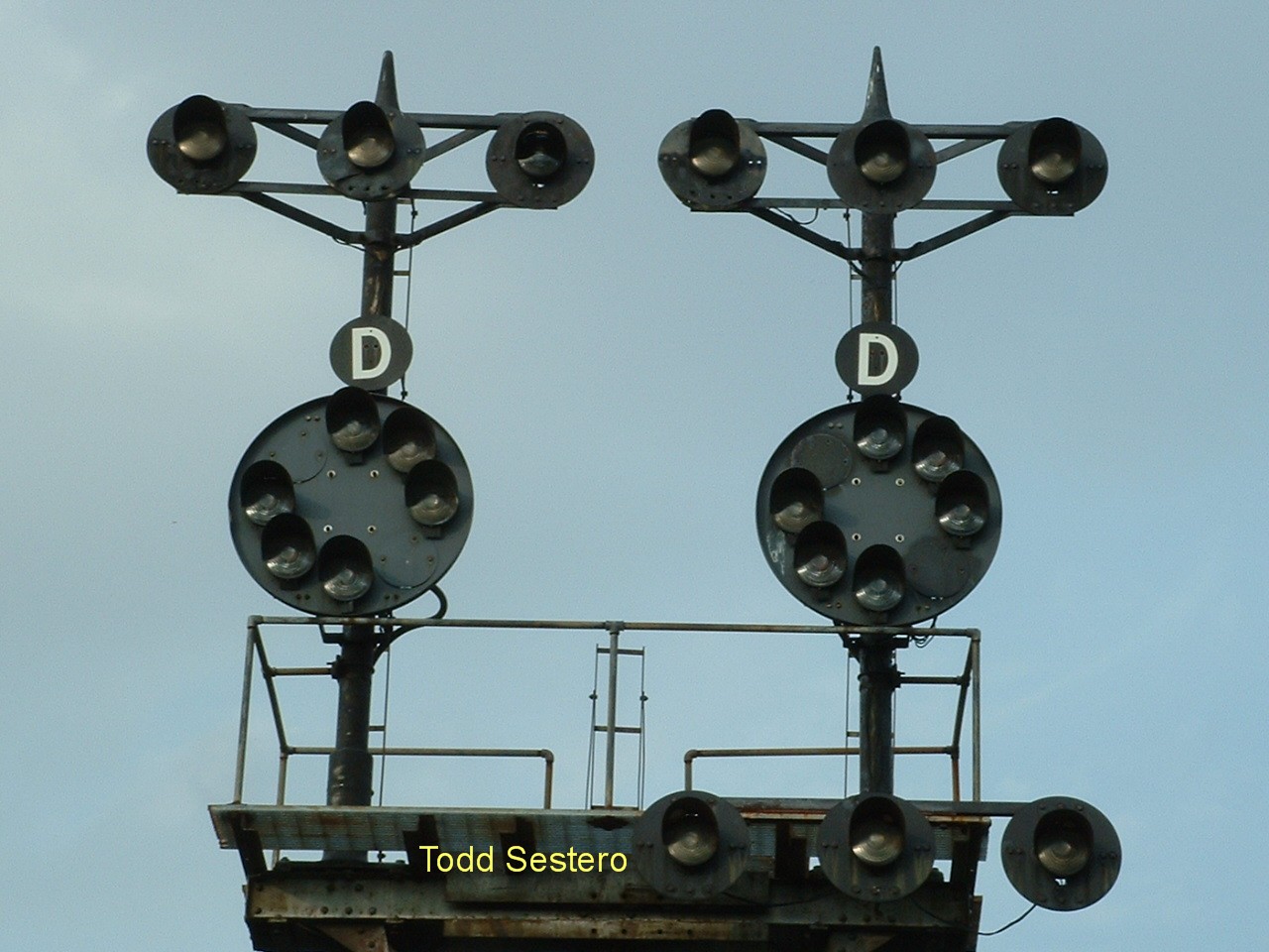
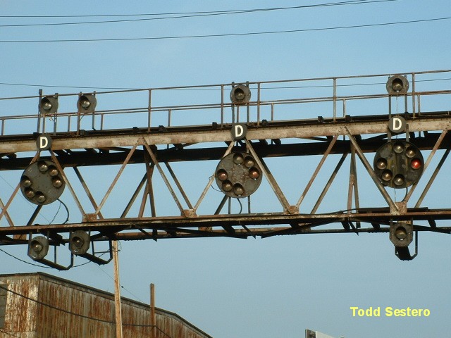
A pair of
back-to-back CPL's in Gaithersburg MD on the CSX mainline heading west to
Brunswick, adjacent to the fairgrounds. The "G" and
"D" signs are for eastbound traffic, such as the pictured freight. The "G"
sign is for "grade", as the freight is starting a downgrade from this
point. The signals are dark in the train picture, because the signals are
approach lit, and there is nothing in that block yet to light them up.... They
will light up once the train has passed the signals and entered that
block. The "D" stands for "delayed in block".
For an explanation of
the "D" signs and why they weren't used until 1996/7, see:
http://www.ntsb.gov/publictn/1997/RAR9702.pdf
Check out pages 38, 43, and 53. These
signals were replaced by colorlights sometime in 2012.
Thanks to
Dave M. of the Yahoo Railway Signaling Group for the info on the "D" sign and
the link to this publication.

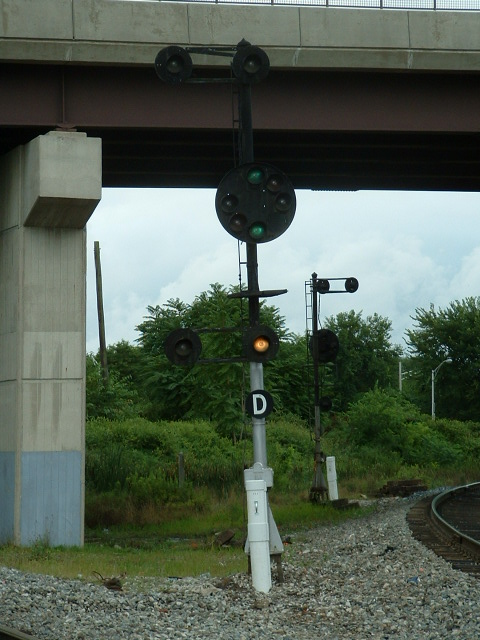
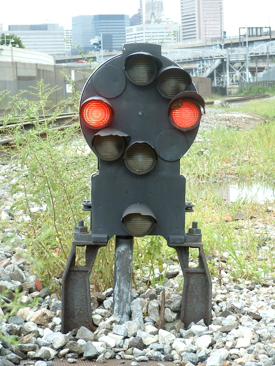
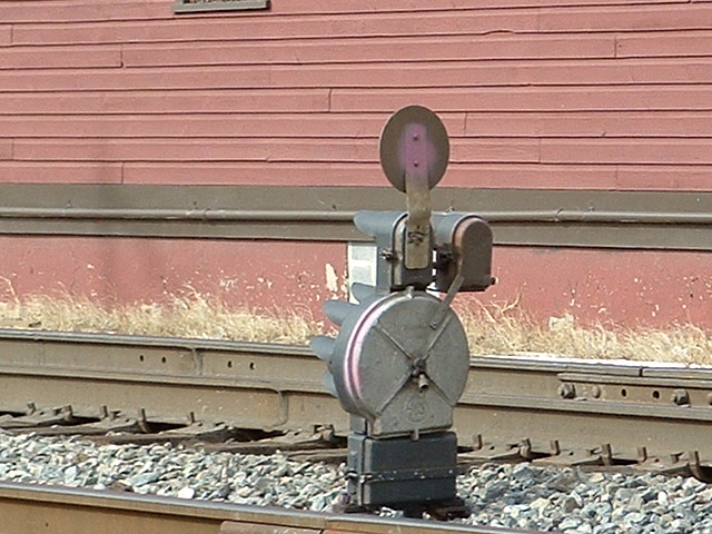
A single aspect, restrict only CPL adjacent to the Westport Light Rail station in south Baltimore.

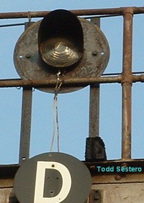
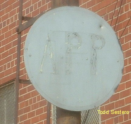 The signal head & approach
sign.
The signal head & approach
sign.


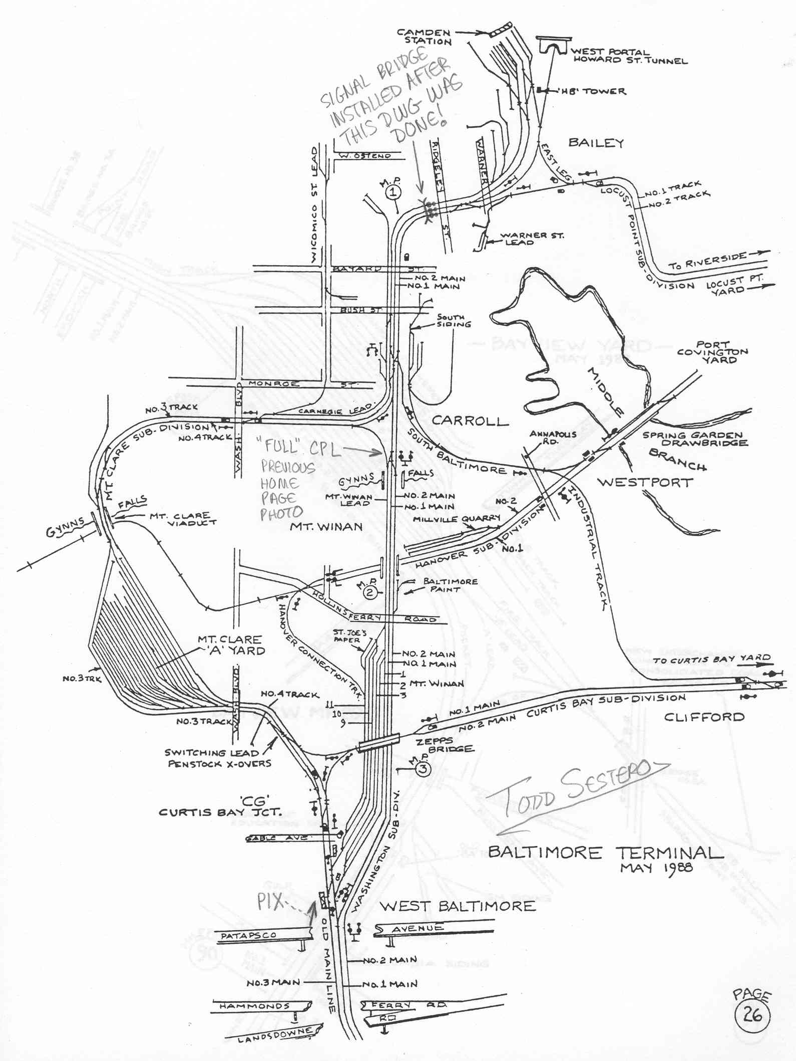 The 3 signals below and Bailey's Wye are
shown on this B&O map of the central Baltimore MD
area.
The 3 signals below and Bailey's Wye are
shown on this B&O map of the central Baltimore MD
area.
South
Baltimore MD - Under I95
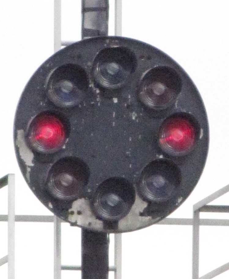
An almost full CPL
The right signal has all 6 markers... the only aspect it is missing is
restricting.


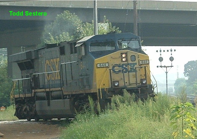 This GE just passed the restrict only
signal above, about a half mile ago.
This GE just passed the restrict only
signal above, about a half mile ago.
Located in south Baltimore along the mainline
to DC at "Carrolls" - can be seen from NB I95 - Pix from
28AUG2005
Replaced by colorlights in 2012.
South
Baltimore MD - Ridgely St
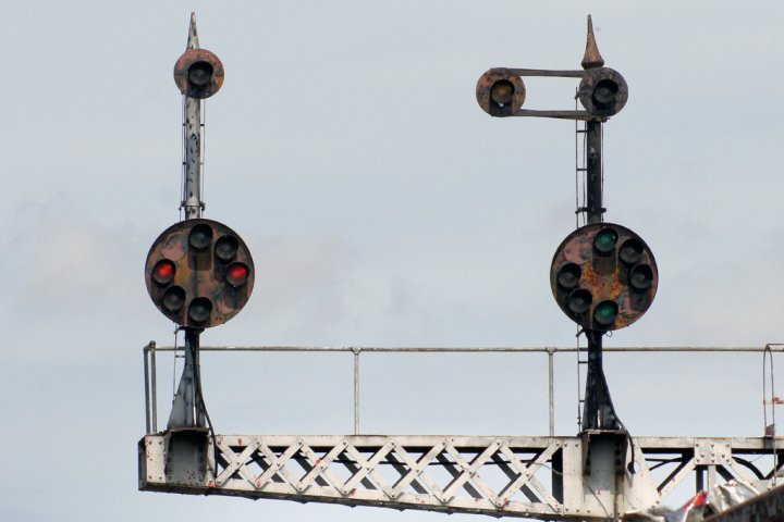
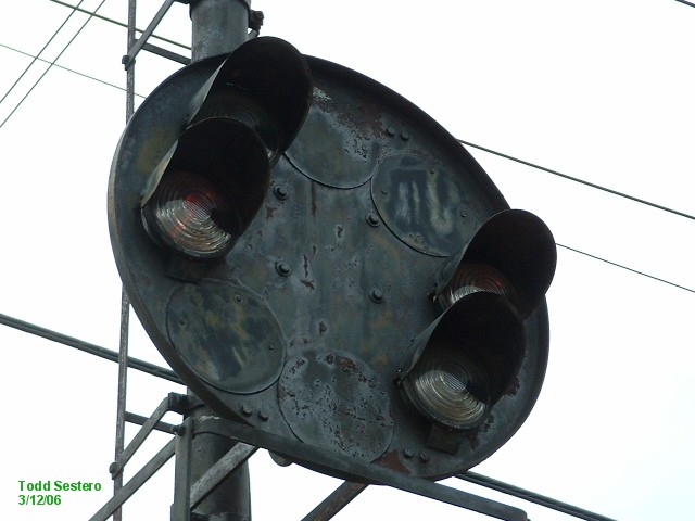
A 3
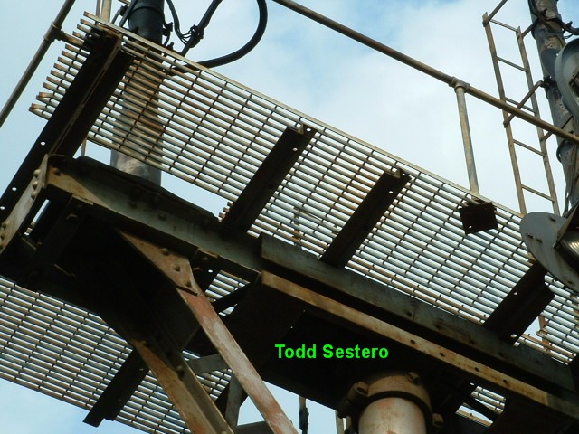
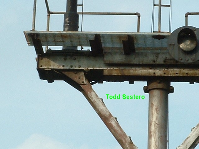
CPL signal bridge - located just south of Baileys Wye 082805
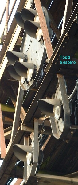


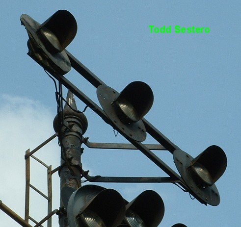
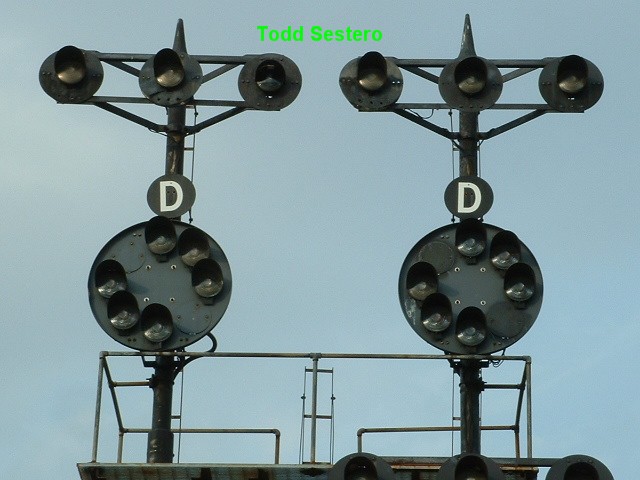
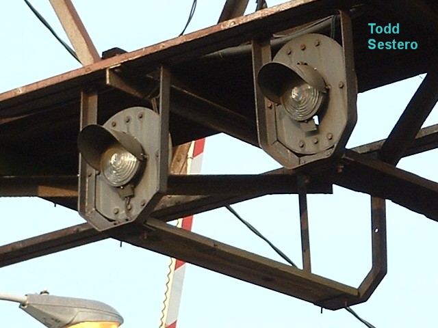
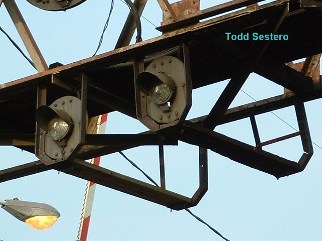
Signal head close-ups.
These heads are the same as the one I have in my
backyard. These things are built to last, as the background is 1/8"
thick. Notice that they are mounted on a slight angle, for the approach to
the bridge is on a curve.

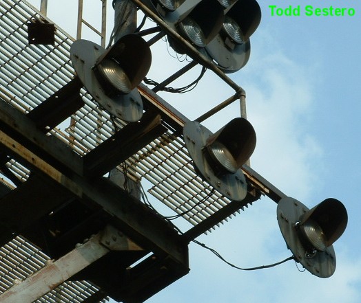
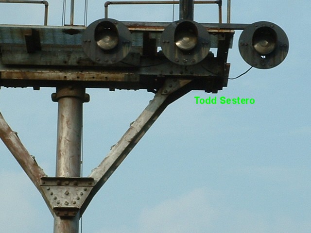
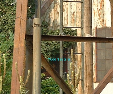
 Marker lamp close-ups.
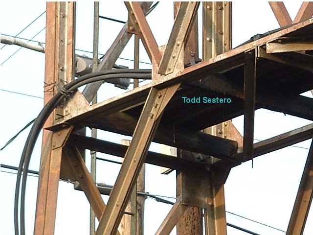
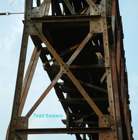
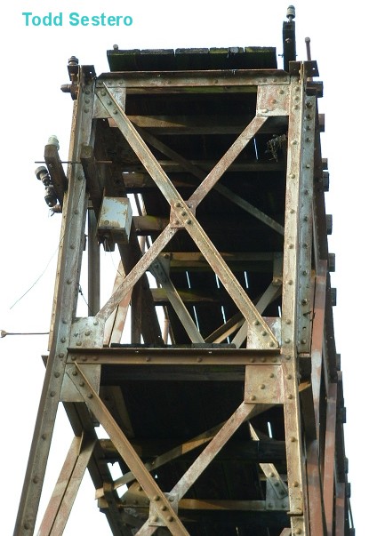
 Signal bridge details.
This signal is located just south of
Camden and Bailey's Wye - It's for northbound traffic.
For the time being, these CPL's, and
others on the south side of the Howard St tunnel have escaped the "Darth Vader"
signal upgrade project. It's not known how much longer these will be
around, so if you like 'em, go out and get your pix now!
It appears (so far) that most of the signals on the mainline between Baltimore and DC are intact, however, two new signal bridges went up in St. Denis/Relay last year, and the signals were cut over towards the end of 2007. CSX was very quick in taking down the two old B&O signals bridges on either side of HX tower. As of November 2013, these signals are in the process of being replaced, the changeover is expected to be in early 2014.
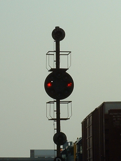
South
Baltimore MD - Below Bush St 1
A CPL signal with 5 markers - for NB reverse traffic on the main line to DC in south Baltimore - 28AUG2005
South
Baltimore MD - Below Bush St 2
A couple of old CPL's placed on a
new cantilever bridge, just north of the signal above. Picture taken in
2005.
This signal is also the same as the one at the top of the page. Sometime in the 2008-2009 timeframe, due to changes CSX made in the interlocking, they changed the left signal and made it a FULL CPL, the only when we are aware of.
South
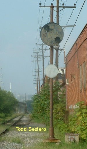
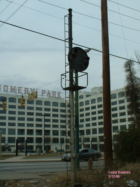
Baltimore MD - Washington Blvd
Two aspect CPL by
Washington Blvd and Monroe St, in south Baltimore


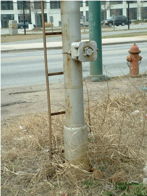
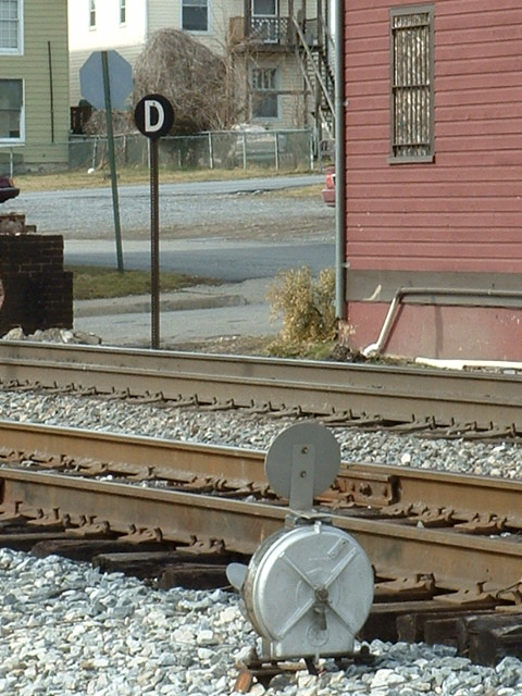
This signal is located just off the
Baltimore-Washington DC main line at Carrolls, it sits across from the old
Montgomery Wards warehouse at Monroe and Washington Blvd. There was once
two tracks thru here, and each track had a high signal for the main traffic
direction and a dwarf CPL for reverse traffic. When they took out the
second track, the CPL's went with it.
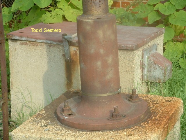
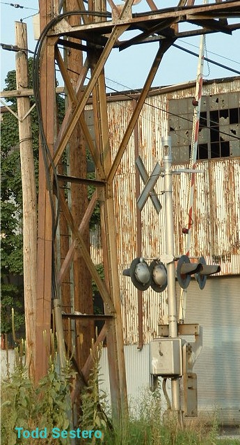
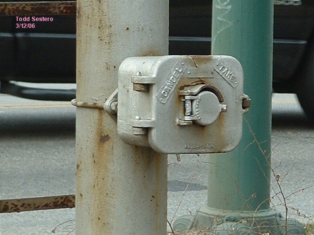
This signal is unique in Baltimore,
in that it has a pole mounted switch to cancel the crossing gates in the event
the train was going to sit at the crossing for any amount of time. There
are two other switches at this location, however, this is the only one mounted
on a signal pole. Pix from 11MAR2006.
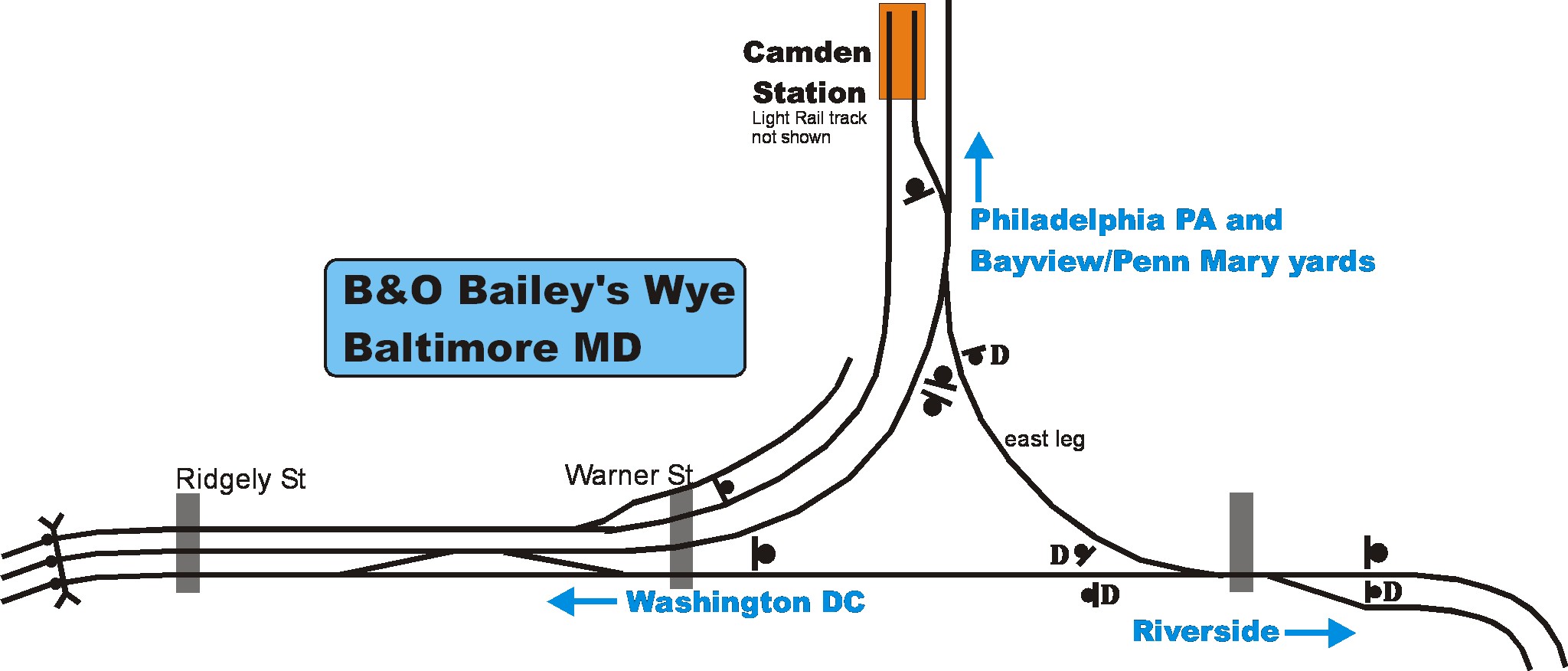 Map of the
Bailey's Wye area
Map of the
Bailey's Wye area
For a more detailed maps of the Baileys Wye area, click HERE.
 CPL on the
SW leg of Bailey's Wye in dntn Baltimore, for freights coming out of Riverside
Yard.
CPL on the
SW leg of Bailey's Wye in dntn Baltimore, for freights coming out of Riverside
Yard.
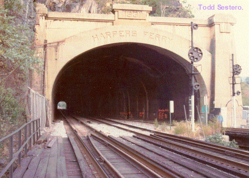
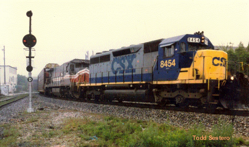
 A couple of
shots of signals on the south side of the Harpers Ferry
tunnel.
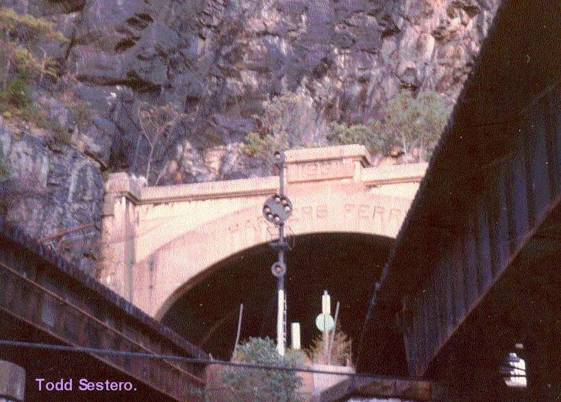
A couple of
shots of signals on the south side of the Harpers Ferry
tunnel.
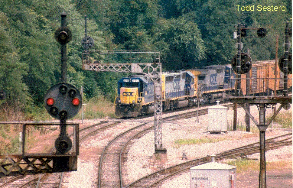
CPL's a plenty at the west (south) end of Mt. Winans
yard in south Baltimore MD, with an approaching westbound CSX freight, taken
around 1995.
Most of these signals were
replaced by "Darth Vader" color light signals in 2007. CPL's around the
curve in Landsdowne were replaced a year or so earlier. The freight is
getting ready to cross Gable Ave, a fairly good photo spot off of Washington
Blvd, near Patapsco (I wouldn't venture into the yard, tho). This freight
might have come from Curtiss Bay if it took the crossover just off the right
side of the pix, if not, it took the long way around coming from Baltimore going
thru Mt. Clare yard A. For a B&O map of the area, click
HERE (same as the map above). The map is dated 1988, but does not
have the signal bridge by Ridgely St on it. Curious. There is a
little arrow on the map along Patapsco Ave that shows where the picture was
taken from. The map covers from Lansdowne Rd on the south side to Camden
Station (before it's current 2 track configuration).
This picture was taken from Gable Avenue, looking towards the place I took the above picture from.
At the bottom, you can see a CPL dwarf. At the top of the photo, and the two bright dots in the middle, are high CPL's. The two large white dots are streetlamps on the bridge that I took the other photo from, and finally, the cluster of three lights is a freight waiting to go into Curtis Bay, sitting under the bridge.
Disclaimers:
I love trains, and I love signals. I am not an expert. My webpages reflect what I find on the topic of the page. This is something I have fun with while trying to help others. My webpages are an attempt at putting everything I can find of the subject in one convenient place. There are plenty of other good websites to help me in this effort, and they are listed in my links section on my indexa page, or as needed on individual pages. Please do not write to me about something that may be incorrect, and then hound the heck out of me if I do not respond to you in the manner you would like. I operate on the "Golden Rule Principle", and if you are not familiar with it, please acquaint yourself with how to treat people by reading Mathew 7:12 (among others, the principle exists in almost every religion). If you contact me (like some do, hi Paul) and try to make it a "non-fun" thing and start with the name calling, your name will go into my spambox list! :-)
If this is a railfan page, every effort has been made to make sure that the information contained on this map and in this railfan guide is correct. Once in a while, an error may creep in, especially if restaurants or gas stations open, close, or change names. Most of my maps are a result of personal observation after visiting these locations. I have always felt that a picture is worth a thousand words", and I feel annotated maps such as the ones I work up do the same justice for the railfan over a simple text description of the area. Since the main focus of my website is railroad signals, the railfan guides are oriented towards the signal fan being able to locate them. Since most of us railheads don't have just trains as a hobby, I have also tried to point out where other interesting sites of the area are.... things like fire stations, neat bridges, or other significant historical or geographical feature. While some may feel they shouldn't be included, these other things tend to make MY trips a lot more interesting.... stuff like where the C&O Canal has a bridge going over a river (the Monocacy Aqueduct) between Point of Rocks and Gaithersburg MD, it's way cool to realize this bridge to support a water "road" over a river was built in the 1830's!!! Beware: If used as a source, ANYTHING from Wikipedia must be treated as being possibly being inaccurate, wrong, or not true.
My philosophy: Pictures and maps are worth a
thousand words, especially for railfanning. Text descriptions only
get you so far, especially if you get lost or disoriented. Take
along good maps.... a GPS is OK to get somewhere, but maps are still
better if you get lost! I belong to AAA, which allows you to get
local maps for free when you visit the local branches. ADC puts
out a nice series of county maps for the Washington DC area, but their
state maps do not have the railroads on them. If you can find em,
I like the National Geographic map book of the U.S..... good, clear, and
concise graphics, and they do a really good job of showing you where
tourist type attractions are, although they too lack the railroads.
Other notes about specific areas will show up on that page if known.
Pictures and additional information is always needed if anyone feels
inclined to take 'em, send 'em, and share 'em, or if you have
something to add or correct.... credit is always given! BE NICE!!! Contact info
is here
Beware: If used as a source, ANYTHING from Wikipedia must be treated as being possibly being inaccurate, wrong, or not true.
RAILFAN GUIDES HOME
RAILROAD SIGNALS HOME
New 10-6-2006
Last
Modified: 02-Oct-2015